In industrial automation, inductive proximity sensors are widely used for non-contact detection of metallic objects. A common feature of these sensors is an LED indicator light, which often blinks under various operating conditions. Understanding what these blinking patterns signify is crucial for maintenance personnel and engineers to ensure optimal system performance and quick troubleshooting.
The blinking light on an inductive proximity sensor typically serves as a status indicator. When the sensor is powered and functioning normally without detecting a target, the LED may emit a steady glow or a slow, rhythmic blink, depending on the manufacturer's design. This indicates that the sensor is operational and awaiting detection. Upon sensing a metallic object within its sensing range, the LED usually switches to a constant on state or changes its blinking pattern—often to a rapid blink or a different color—to confirm detection. This immediate visual feedback is invaluable during setup and alignment, allowing technicians to verify the sensor's responsiveness without relying solely on control system readouts.
However, a blinking light can also signal issues. For instance, a fast, irregular blink might indicate problems such as voltage fluctuations, wiring faults, or sensor misalignment. Many modern sensors are equipped with diagnostic capabilities, using specific blink codes to denote errors like short circuits, overload conditions, or temperature extremes. Consulting the sensor's datasheet is essential to decode these patterns accurately. For example, three short blinks followed by a pause could signify an output overload, while continuous rapid blinking might point to an unstable power supply.
Environmental factors can also influence the LED behavior. In high-vibration settings, loose connections may cause intermittent blinking. Similarly, electromagnetic interference (EMI) from nearby motors or frequency drives can disrupt sensor operation, leading to erratic LED indicators. Ensuring proper shielding, secure mounting, and adherence to specified voltage ranges—commonly 10-30V DC for many models—can mitigate these issues. Regular maintenance checks should include inspecting the LED patterns as a first step in diagnostics.
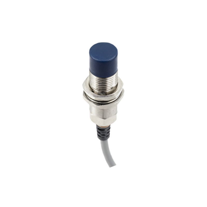
Furthermore, some advanced sensors feature programmable blinking modes for customization. Users can set the LED to blink only on detection, remain off during normal operation to reduce power consumption, or activate specific patterns for diagnostic purposes. This flexibility enhances integration into complex automated systems where visual indicators must align with broader machine status protocols.
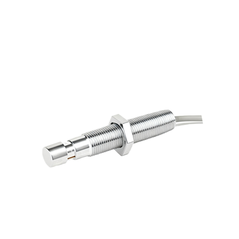
In summary, the blinking light on an inductive proximity sensor is more than a simple power indicator—it is a critical communication tool. By interpreting its patterns correctly, engineers can swiftly identify operational states, confirm detection accuracy, and diagnose potential faults. Always refer to the manufacturer's documentation for model-specific blink codes, and incorporate LED monitoring into routine maintenance schedules to preempt failures and sustain productivity in industrial environments.