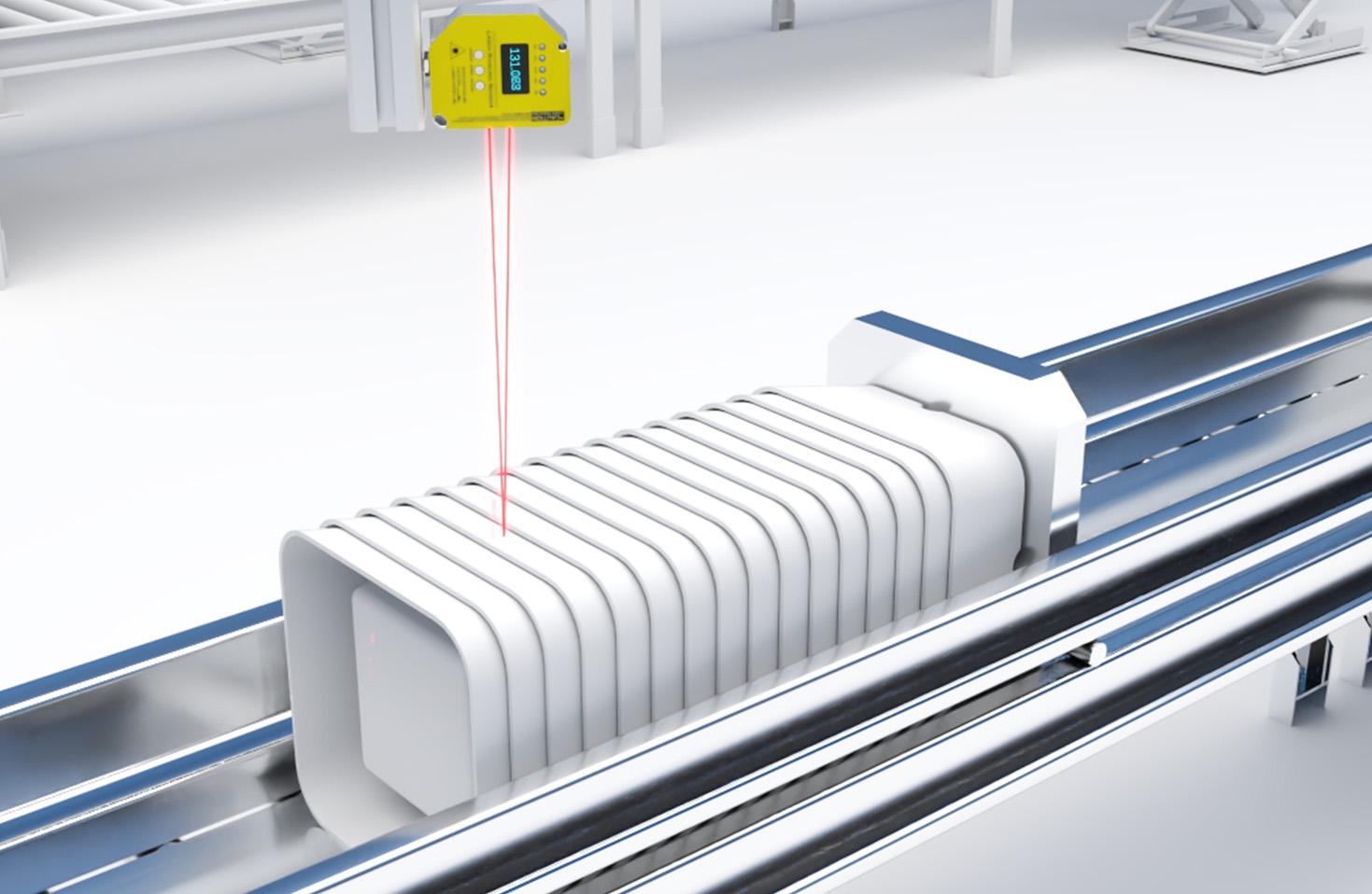
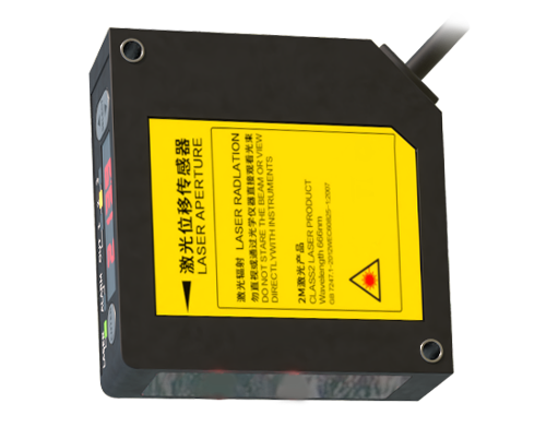
In the realm of industrial automation and precision engineering, laser displacement sensors have become indispensable tools for non-contact measurement. Their ability to deliver high-accuracy, high-speed readings across various materials and surfaces makes them superior to many traditional contact-based methods. At the core of their functionality lies the principle of displacement measurement, a sophisticated interplay of optics, electronics, and signal processing. This article delves into the fundamental working principles of common laser displacement sensors, primarily focusing on the triangulation method and the time-of-flight (ToF) principle.
The most prevalent technology in high-precision, short-to-medium-range applications is laser triangulation. The basic setup involves three key components: a laser diode, a lens, and a position-sensitive detector (PSD) or a Charge-Coupled Device (CCD)/CMOS linear image sensor. The process begins when the laser diode emits a focused beam of coherent light onto the target surface. The spot of light is then diffusely reflected from the surface. A receiving lens, positioned at a known angle (the triangulation angle) relative to the laser emitter, collects a portion of this scattered light and projects it onto the sensitive area of the PSD or image sensor.
The fundamental principle is geometric triangulation. When the target object moves closer to or farther from the sensor (changing its distance, or displacement), the position of the reflected light spot on the detector shifts correspondingly. If the object moves closer, the spot moves in one direction on the detector; if it moves farther away, the spot moves in the opposite direction. This positional change on the detector is precisely measured. Using the known fixed baseline distance between the laser emitter and the receiving lens, and the known triangulation angle, the sensor's internal processor calculates the exact distance to the target via trigonometric functions. This method provides exceptional resolution, often in the micron or sub-micron range, but is best suited for controlled environments with relatively diffuse surfaces.
For longer-range measurements or applications requiring very high measurement speeds, the Time-of-Flight (ToF) principle is often employed. This method is conceptually simpler but requires extremely precise timing electronics. A pulsed laser diode emits a short burst of light towards the target. The light reflects off the surface and returns to a photodetector adjacent to the emitter. The sensor precisely measures the time delay (Δt) between the emission of the pulse and the detection of its return. Since the speed of light (c) is a constant, the distance (d) to the target can be calculated using the formula: d = (c * Δt) / 2. The division by two accounts for the round-trip journey of the light pulse. Continuous-wave ToF systems modulate the laser beam with a high-frequency signal and measure the phase shift between the emitted and reflected light to calculate distance. ToF sensors are robust for longer ranges and less sensitive to surface color or texture variations, though their absolute accuracy is typically lower than that of triangulation sensors for short distances.
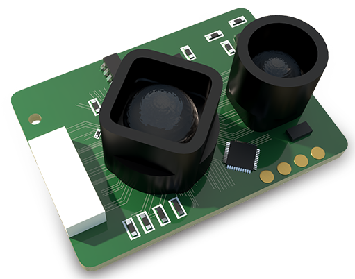
Several critical factors influence the performance and accuracy of laser displacement sensors. The target surface characteristics are paramount. Ideal diffuse surfaces (e.g., matte white paint) provide stable, reliable reflections. Specular (shiny) surfaces can cause erroneous reflections, while dark or absorbing materials may return too weak a signal. Advanced sensors employ techniques like using a coaxial optical path (where emission and reception share the same axis) to better handle specular surfaces. Environmental conditions such as ambient light, dust, fog, or temperature fluctuations can also interfere with the laser beam or detector, necessitating protective housings, optical filters, or temperature compensation circuits.
In practical industrial applications, laser displacement sensors are configured for various measurement modes: thickness measurement by using two opposing sensors, vibration analysis by capturing high-speed displacement changes, and profile scanning by moving the sensor or the target. Their versatility drives their use in quality control (e.g., checking part dimensions, warp, or presence), robotics (guidance and positioning), and semiconductor manufacturing.
In conclusion, the displacement measurement principle of laser sensors, whether based on precise optical triangulation or high-speed time-of-flight calculation, translates minute physical changes into highly accurate digital data. Understanding these principles allows engineers to select the appropriate sensor type, configure it correctly, and mitigate potential error sources, thereby ensuring reliable and precise measurement in demanding automation and research environments. The continuous evolution of laser and detector technology promises even greater capabilities, solidifying the role of these sensors as pillars of modern metrology.