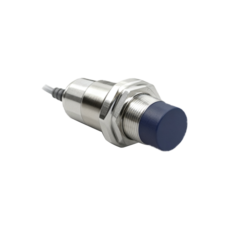
Infrared proximity sensors are widely utilized across various industries for object detection, distance measurement, and automation control. Understanding the internal components and their interplay through a functional diagram is essential for engineers and technicians working with these devices. This article delves into the key elements that constitute a typical infrared proximity sensor, illustrated via a detailed component layout, and explains how each part contributes to the sensor's overall operation.
At the core of an infrared proximity sensor lies the infrared emitter, usually an infrared LED (Light Emitting Diode). This component emits infrared light, which is invisible to the human eye but detectable by electronic receivers. The wavelength of the emitted IR light typically ranges between 850 nm to 950 nm, optimized for common sensing applications. The emitter is driven by a current-limiting circuit to ensure stable output and longevity. Adjacent to the emitter is the infrared receiver, often a photodiode or phototransistor. This receiver detects the reflected IR light from objects within the sensor's range. Its sensitivity is crucial for accurate detection, and it is often paired with a filter to minimize interference from ambient light sources, such as sunlight or artificial lighting.
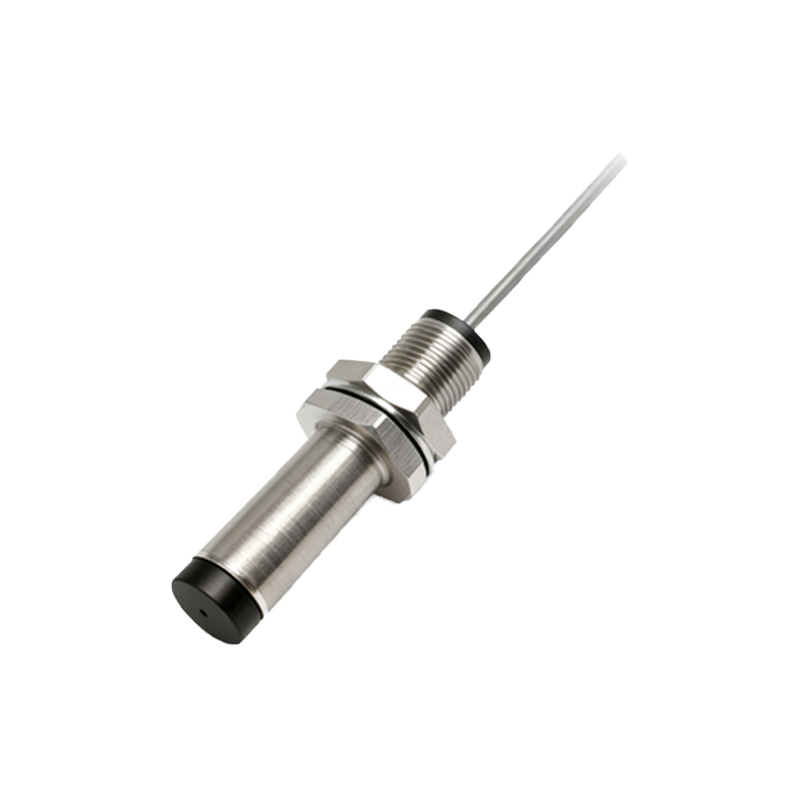
The optical components play a pivotal role in directing and focusing the infrared beams. A lens or reflector assembly is commonly employed to collimate the emitted light into a narrow beam, enhancing the sensor's directivity and range. Similarly, the receiver side may incorporate a lens to concentrate reflected light onto the photodetector, improving signal strength and signal-to-noise ratio. The housing design, which includes apertures and barriers, helps isolate the emitter and receiver to prevent internal crosstalk, ensuring that the sensor primarily responds to external reflections.
Supporting electronics form the backbone of signal processing. A typical block diagram includes an oscillator or modulator circuit that pulses the IR emitter at a specific frequency, often in the range of a few kilohertz to several tens of kilohertz. This modulation allows the sensor to distinguish between the emitted signal and ambient IR noise, significantly boosting reliability. The receiver's output is fed into a demodulator and amplifier stage, which filters out unwanted frequencies and amplifies the weak reflected signal. Following this, a comparator circuit evaluates the amplified signal against a predefined threshold to determine the presence or absence of an object. Some advanced sensors integrate microcontrollers for digital processing, enabling features like adjustable sensitivity, output formatting (digital or analog), and communication protocols (e.g., I2C, UART).
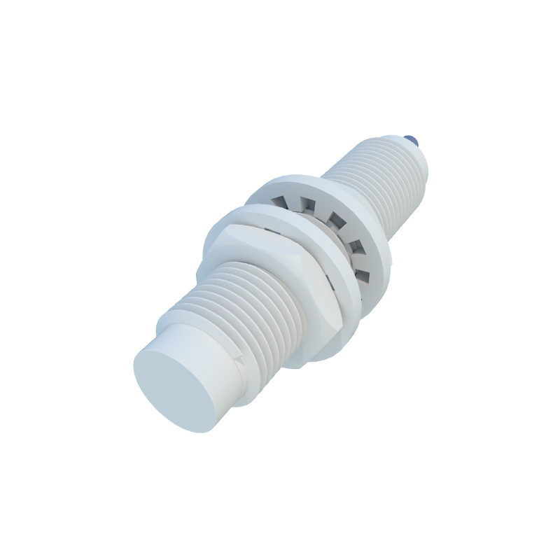
Power management circuits are integral, providing regulated voltage to all components. These may include voltage regulators, capacitors for noise suppression, and protection diodes against reverse polarity or voltage spikes. The output interface varies based on application needs, ranging from simple open-collector transistors for switch-like behavior to analog voltage outputs proportional to distance.
In a functional diagram, these components are interconnected through clear pathways showing signal flow: from power input to oscillator, emitter, receiver, amplifier, comparator, and finally to the output stage. Such diagrams often highlight feedback loops for automatic gain control or calibration, which adapt the sensor's performance to environmental changes. Engineers rely on these diagrams for troubleshooting, design integration, and optimizing sensor placement in systems like robotics, automotive safety, industrial automation, and consumer electronics.
Understanding the composition through a diagram not only aids in selection and application but also underscores the importance of each component in achieving precise, non-contact detection. As technology advances, innovations in miniaturization, power efficiency, and smart sensing continue to evolve, yet the fundamental principles depicted in these component layouts remain foundational for professionals in the electrical and automation fields.