Proximity sensors are fundamental components in modern industrial automation and electrical control systems. Their ability to detect the presence or absence of an object without physical contact makes them indispensable for tasks ranging from simple object counting to complex position feedback in machinery. This article delves into the working principle diagram of a standard inductive proximity sensor, the most common type, and explains its core operational stages in detail.
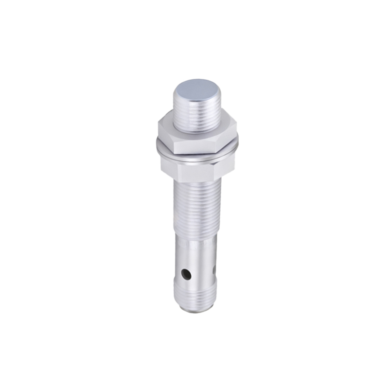
The core of an inductive proximity sensor is a high-frequency oscillator circuit, a detection circuit, and an output circuit, all housed within a robust casing. The principle diagram typically illustrates these components and their interconnections. At the heart of the oscillator is a coil of wire wound around a ferrite core, which creates an electromagnetic field at the sensor's active face when energized. This oscillating field is contained within a small, defined area in front of the sensor.
When no metallic target is within this detection range, the oscillator circuit continues to run at its designed amplitude. The detection circuit, which monitors the oscillator's strength, sees a stable signal and does not trigger a change in the output state. The output, whether it is a PNP (sourcing), NPN (sinking), or a relay contact, remains in its normal, non-activated condition.
The critical operation begins when a conductive (typically metallic) target enters the sensor's electromagnetic field. According to Faraday's law of electromagnetic induction, eddy currents are induced on the surface of the target object. These circulating currents create their own magnetic field, which opposes the original field generated by the sensor's coil. This opposition results in a phenomenon known as "loading" of the oscillator.
The detection circuit is precisely tuned to sense this change in oscillator amplitude or frequency. As the target moves closer, the eddy current effect increases, causing a greater load on the oscillator. Once this loading reaches a predetermined threshold—corresponding to the sensor's nominal sensing distance (Sn)—the detection circuit sends a signal to the output stage. This signal commands the output switching device (like a transistor) to change state. For a normally open (NO) sensor, the output turns ON, allowing current to flow to the connected load, such as a PLC input, relay coil, or indicator lamp.
A key feature shown in the principle diagram is the hysteresis zone. This is a small differential between the switch-on point (as the target approaches) and the switch-off point (as the target recedes). Hysteresis prevents rapid, chattering output signals if the target were to hover precisely at the sensing edge, ensuring stable and reliable switching. The diagram often marks the effective sensing distance (Sn) and the assured operating distance, which is typically 90% of Sn to account for manufacturing tolerances and environmental factors like temperature.
Beyond the basic inductive type, the working principle diagram for a capacitive proximity sensor is similar but relies on changes in capacitance. Its active face forms one plate of a capacitor, with the target (which can be metallic or non-metallic, liquid, or granular) acting as the other plate. As the target nears, the capacitance increases, altering the state of an internal RC oscillator circuit, which in turn triggers the output switch.
Understanding the schematic of a proximity sensor's internal circuitry is crucial for electrical engineers. It aids in proper sensor selection based on factors like target material, required sensing distance, output type, and environmental conditions. It also facilitates effective troubleshooting. For instance, if a sensor fails to detect a target, referencing the principle diagram guides the engineer to check the power supply to the oscillator, potential shielding issues from other metal objects, or wear and tear on the sensor face that could dampen the electromagnetic field. Mastery of this fundamental diagram ensures reliable integration of these devices into control panels, automated production lines, and safety systems, forming the backbone of responsive and efficient electrical automation.