In industrial automation and control systems, proximity switch sensors are indispensable components for non-contact detection of metallic or non-metallic objects. Their reliability hinges significantly on correct wiring. Among the various types, 3-wire sensors are the most prevalent, offering a robust balance of performance and simplicity. This guide delves into the standard 3-wire connection methods, providing clear instructions and essential considerations for engineers and technicians.
A standard 3-wire proximity sensor typically has wires color-coded as Brown, Blue, and Black. While color codes can vary slightly by manufacturer (always consult the datasheet), the Brown wire is universally for the positive supply voltage (+V), the Blue wire for the common negative or ground (0V), and the Black wire for the output signal. The core of the wiring method depends on the sensor's output type: PNP (sourcing) or NPN (sinking).
PNP (Sourcing) Output Wiring:
A PNP sensor acts as a sourcing device. In this configuration, the Brown wire connects to the positive terminal of the DC power supply (typically +24VDC). The Blue wire connects to the negative terminal (0V). The Black output wire provides the positive voltage signal. When the sensor detects a target, it switches the Black wire to the supply voltage (+V), effectively "sourcing" current to the load. The load (e.g., a PLC input, relay coil) is connected between the Black wire and the power supply's negative (0V). This method is commonly used in European and many global standards.
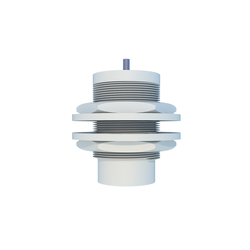
NPN (Sinking) Output Wiring:
An NPN sensor acts as a sinking device. Here, the Brown and Blue wires are connected identically: Brown to +V and Blue to 0V. The critical difference lies in the Black output wire. In an NPN sensor, the output acts as a path to ground. The load must be connected between the positive supply (+V) and the Black wire. When the sensor activates, it switches the Black wire to ground (0V), "sinking" current from the load through the sensor to ground. This configuration is often preferred in Asian and some North American applications.
Crucial Steps and Safety Considerations:
1. Power Verification: Always confirm the sensor's operating voltage range (e.g., 10-30VDC) before connecting it to a power supply. Applying incorrect voltage is a primary cause of failure.
2. Polarity Check: Double-check the polarity of your DC power supply connections. Reversing polarity on a DC sensor will likely damage it permanently.
3. Load Matching: Ensure the load (the device being controlled) is compatible with the sensor's output specifications. Check the maximum output current the sensor can handle. Exceeding this rating can destroy the output transistor. For inductive loads like relays, always use a protective flyback diode.
4. Wiring Integrity: Use proper gauge wires and secure connections. Loose connections cause intermittent operation and voltage drops. In electrically noisy environments, use shielded cables, connecting the shield to ground at only one end to prevent ground loops.
5. Sensor Type Confirmation: Never assume the output type. Clearly identify if the sensor is PNP or NPN from its model number or labeling. Connecting a PNP load to an NPN sensor (or vice versa) will result in a non-functional circuit.
6. Testing: After wiring, perform a functional test. Use a multimeter to verify that the output voltage on the Black wire switches correctly (from ~0V to near supply voltage for PNP, or from supply voltage to ~0V for NPN) when a target enters the sensing range.
Advanced Connection Scenarios:
For more complex control logic, sensors can be wired in series or parallel. Wiring PNP sensors in series creates an AND logic; all must be active for the circuit to be complete. Wiring NPN sensors in parallel creates an OR logic; any one active will complete the circuit to ground. Always consider the cumulative voltage drops and current draws in such configurations.
In summary, mastering the 3-wire connection for proximity sensors—distinguishing between PNP and NPN outputs—is fundamental. Correct wiring ensures not only operational success but also system longevity and safety. Adherence to manufacturer datasheets, methodical installation, and thorough testing form the cornerstone of effective sensor integration in any control panel or automated machinery.