For engineers and technicians working with industrial automation and safety systems, the precise configuration of proximity sensors is paramount. The 13pm series of inductive proximity sensors, known for their robustness and reliability in detecting metallic objects, requires correct parameter setting for optimal performance. This guide details the location and methodology for configuring these critical devices.
The primary configuration interface for the 13pm sensor is not on the sensor housing itself. Unlike some sensor families with integrated potentiometers or push-button setups, the 13pm series typically relies on external devices for parameter adjustment. The core settings, such as sensing distance compensation, output function (NO/NC), and response time, are often configured via the connected programmable logic controller (PLC) or a dedicated sensor amplifier/controller unit.
In a standard setup, the 13pm sensor is connected to a compatible amplifier like the corresponding manufacturer's interface module. The physical configuration point is located on this amplifier unit. Engineers must access the amplifier's housing, which features a series of DIP switches, a rotary selector, or a digital display with membrane buttons. The exact layout is model-specific. For instance, on a common companion amplifier, a bank of DIP switches is used to set the operating mode (e.g., damped or undamped operation for precise positioning) and the output logic. A separate rotary switch might be employed for fine-tuning the sensitivity or the detection threshold, effectively adjusting the effective sensing range within the sensor's specified limits.
For systems integrated with a PLC, the configuration becomes software-based. The sensor's output is wired to a PLC input module. The critical parameters are then set within the PLC programming environment (e.g., ladder logic or structured text). Here, you can configure timers for on-delay or off-delay functions, create window comparators for sensing range limits, and implement logic for the output signal. The "setting" is therefore within the PLC program, and the physical location is the engineering workstation or HMI used to upload the logic to the controller.
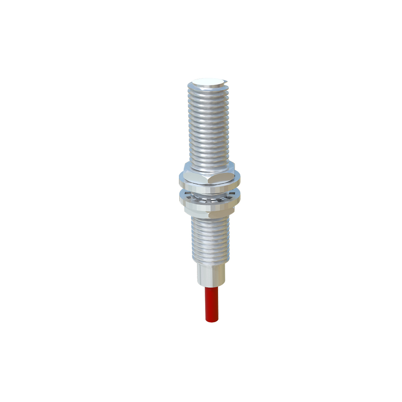
Furthermore, some advanced 13pm models with IO-Link capability offer a different paradigm. Configuration is performed digitally through the IO-Link master port. Using dedicated configuration software on a PC connected to the IO-Link master, engineers can remotely read and write all sensor parameters. This includes not only basic settings but also diagnostic data and process values. The configuration point in this scenario is virtually within the software interface, providing the most flexible and detailed setup environment.
In summary, to configure a 13pm proximity sensor, one must look to the associated control electronics. The key locations are: 1) the DIP switches or rotary selectors on the dedicated sensor amplifier; 2) the program logic and data tables within the connected PLC system; or 3) the parameterization software for IO-Link enabled models. Always consult the specific 13pm model datasheet and the amplifier/controller manual for the precise switch functions, address maps, or software commands. Proper configuration at these points ensures reliable object detection, prevents nuisance tripping, and maintains the integrity of the automated system's safety and operational loops.