In modern industrial automation systems, precise motor speed control is critical for optimizing production efficiency, ensuring product quality, and reducing energy consumption. Among various sensing technologies, proximity sensors have emerged as a reliable and versatile solution for monitoring rotational speed and enabling dynamic control of electric motors. This article explores the principles, implementation methods, and practical applications of using proximity sensors for motor speed regulation.
Proximity sensors, including inductive, capacitive, and magnetic types, detect the presence or absence of a target object without physical contact. When applied to motor speed control, these sensors are typically mounted near a rotating component, such as a motor shaft or a coupled gear. A metallic or ferrous target, often in the form of a key, notch, or dedicated disc with multiple teeth, is attached to the rotating part. Each time the target passes the sensor, it generates a pulse signal. The frequency of these pulses is directly proportional to the rotational speed of the motor.
The core control system consists of three main stages: sensing, processing, and actuation. In the sensing stage, the proximity sensor outputs a digital or analog signal corresponding to the target's passage. This raw signal is then conditioned to eliminate noise and ensure a clean, consistent pulse train. The processing stage involves a microcontroller, programmable logic controller (PLC), or dedicated speed controller. This unit calculates the actual speed by measuring the time interval between consecutive pulses or counting pulses over a fixed time window. The calculated speed is compared to a predefined setpoint or a reference signal from a supervisory system.
Based on this comparison, the controller generates a corrective output. For AC motors, this often involves adjusting the frequency and voltage via a variable frequency drive (VFD). For DC motors, the output typically modulates the armature voltage or the duty cycle of a pulse-width modulation (PWM) signal. The actuation stage executes this command, altering the power supplied to the motor to increase or decrease its speed, thereby closing the control loop. This forms a feedback control system, commonly a proportional-integral-derivative (PID) loop, which continuously minimizes the error between the desired and actual speed.
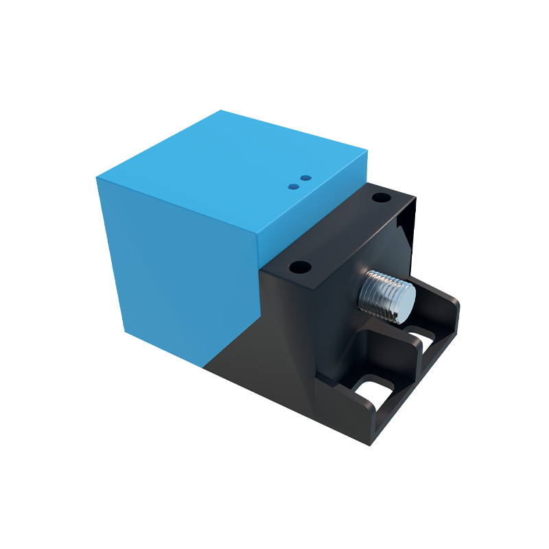
The advantages of using proximity sensors for this purpose are significant. They offer high resolution and accuracy, capable of detecting very high speeds with minimal lag. Their non-contact nature eliminates mechanical wear, ensuring long-term reliability and reduced maintenance in harsh industrial environments characterized by dust, moisture, or vibration. Furthermore, their simple installation and compatibility with standard industrial communication protocols (e.g., IO-Link, PROFINET) facilitate integration into existing automation networks.
Practical applications are widespread across industries. In conveyor systems, proximity sensors help maintain consistent belt speed, synchronizing multiple sections to prevent material pile-up or stretching. In packaging machinery, they ensure precise speed matching between filling stations and sealing units. CNC machining centers utilize them to monitor spindle speed for optimal cutting conditions, while in pumping stations, they regulate flow rates by controlling pump motor speed. A key implementation example involves a centrifugal fan system where an inductive proximity sensor monitors a fan shaft. The controller uses this speed feedback to adjust the VFD, maintaining the required air volume despite varying duct pressure, leading to substantial energy savings.
When designing such a system, several factors must be considered. Sensor selection is paramount; inductive sensors are ideal for metallic targets in dirty environments, while magnetic sensors might be preferred for very high speeds. The number of targets per revolution determines the resolution; more targets provide finer speed detection but require a sensor with a sufficient response frequency. Mounting must be precise to ensure consistent signal strength and avoid false triggers. Environmental factors like temperature extremes, electromagnetic interference (EMI), and the presence of other metallic objects can affect sensor performance and must be mitigated through proper shielding and installation practices.
In conclusion, integrating proximity sensors into motor speed control loops provides a robust, accurate, and maintenance-friendly solution for industrial automation. By delivering real-time rotational feedback, they enable sophisticated control strategies that enhance process stability, improve product consistency, and promote operational efficiency. As Industry 4.0 advances, the role of such sensor-based feedback systems will only grow, forming the foundational layer for data-driven predictive maintenance and intelligent machine control.