In industrial automation and precision measurement, laser sensors are indispensable components, prized for their accuracy, speed, and non-contact operation. However, a common and often perplexing issue encountered by engineers and maintenance personnel is the sensor's failure to trigger or register a detection event. This non-triggering state can halt production lines, compromise quality control, and lead to significant downtime. This article delves into the root causes, systematic diagnostic approaches, and practical solutions for resolving laser sensor non-triggering problems.
The fundamental principle of a photoelectric laser sensor involves emitting a focused laser beam towards a target. The sensor's receiver then detects either the presence of the reflected beam (diffuse or retro-reflective models) or the interruption of the beam (through-beam models). A non-triggering condition essentially means the sensor's output does not change state (e.g., from OFF to ON) when the target is present within its specified sensing range. The causes are multifaceted and can be categorized into environmental, mechanical, electrical, and sensor-specific factors.
Primary Causes of Non-Triggering:
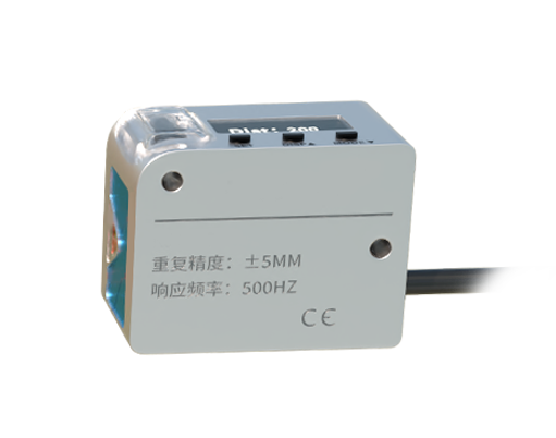
1. Environmental Interference: Contamination is a leading culprit. Dust, oil mist, steam, or other particulates in the air can scatter or absorb the laser beam, attenuating its intensity below the receiver's detection threshold. Similarly, intense ambient light—such as direct sunlight, welding arcs, or high-intensity discharge lamps—can flood the receiver, causing it to ignore the modulated laser signal. Extreme temperatures outside the sensor's operating specification can also affect electronic component performance and laser diode output.
2. Target-Related Issues: The sensor may be functioning correctly, but the target itself is unsuitable. Problems include:
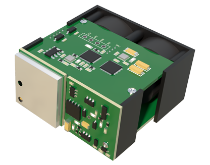
* Low Reflectivity: The target material (e.g., matte black rubber, dark cloth, transparent glass) may not reflect enough light back to the receiver in diffuse mode sensors.
* Small Size/Angle: The target might be too small or presented at an acute angle, failing to reflect sufficient light into the receiver's aperture.
* Incorrect Positioning: The target may be outside the sensor's effective sensing window or spot size, or it may be vibrating excessively, causing intermittent detection.
3. Optical Path Obstruction: In through-beam systems, misalignment is the most frequent cause. Even a minor physical bump can misalign the separate emitter and receiver units. For reflective types, the reflective tape or mirror may be dirty, damaged, or misaligned. The lens windows on both the emitter and receiver can become coated with grime, drastically reducing light transmission.
4. Electrical and Configuration Errors: These are often overlooked but critical.
* Power Supply Issues: Voltage outside the specified range (e.g., 10-30 VDC), excessive ripple, or incorrect polarity can prevent proper operation.
* Wiring Faults: Loose connections, broken wires, or short circuits in the output circuit (e.g., NPN vs. PNP sourcing/sinking) will disrupt the signal.
* Incorrect Settings: The sensor's sensitivity threshold may be set too high. The operating mode (light-on/dark-on) might be configured opposite to the application's logic. Timer functions (ON-delay, OFF-delay) could be masking the expected trigger response.
5. Sensor Degradation or Damage: Over time, the laser diode's output power can degrade. The receiver phototransistor may lose sensitivity. Physical damage from impact, moisture ingress (leading to corrosion), or electrical surges can cause internal component failure.
Systematic Troubleshooting Methodology:
A logical, step-by-step approach is essential to isolate the fault efficiently.
1. Visual Inspection: Power down the system if safe. Inspect the sensor, target, and optical path for obvious dirt, damage, or misalignment. Clean lenses and reflectors with appropriate materials.
2. Verify Power and Wiring: Using a multimeter, confirm the supply voltage at the sensor's terminals is correct and stable. Check wiring against the datasheet diagram for both power and output connections.
3. Simplify and Isolate: If possible, create a controlled test. Remove the sensor from the complex application. Use a standard, highly reflective target (like white paper) at the recommended sensing distance. This eliminates environmental and target variables.
4. Utilize Indicator LEDs: Most laser sensors have power (PWR) and output (OUT) status LEDs. Observe their behavior. A solid PWR LED indicates good power. An OUT LED that changes state when a target is introduced in the test setup confirms basic sensor function, pointing the problem elsewhere (e.g., wiring to the PLC). If the OUT LED does not change, the issue lies with the sensor's detection capability.
5. Check Configuration: Consult the manual. Temporarily set the sensitivity to its maximum (most sensitive) setting for testing. Verify the light-on/dark-on mode. Disable any special functions like window mode or extended timers.
6. Monitor Output Signal: Use an oscilloscope or a multimeter with a frequency function to observe the sensor's output signal directly at its terminals while introducing a target. This confirms whether the sensor is switching electrically, independent of the downstream controller.
7. Environmental Control: Shield the sensor from ambient light. For through-beam sensors, perform a careful realignment procedure, often indicated by an alignment LED or signal strength meter on the device.
Preventive Measures and Best Practices:
Prevention is always more cost-effective than troubleshooting. Implement regular cleaning schedules for optical components. Ensure sensors are mounted securely with vibration-damping fixtures where necessary. Use protective housings (NEMA/IP rated) in harsh environments. Always provide a clean, regulated power supply with surge protection. During installation, carefully follow alignment procedures and configure settings according to the specific application requirements, not default values. Keep a log of sensor performance and environmental conditions to identify degrading trends before failure occurs.
By understanding these principles and adopting a structured diagnostic routine, engineers can swiftly restore functionality, minimize unplanned downtime, and ensure the reliable operation that modern automated systems demand from their laser sensing components.