In the realm of industrial automation and control systems, proximity switch sensors are indispensable components for non-contact detection of metallic and, in some cases, non-metallic objects. Their integration into complex machinery for positioning, counting, and safety applications is ubiquitous. A critical aspect of modern sensor design and functionality, particularly for output signal conditioning and interface with programmable logic controllers (PLCs) or microcontrollers, is the use of Pulse Width Modulation (PWM). This article delves into the technical principles, implementation, and practical considerations of PWM outputs in proximity sensors.
At its core, Pulse Width Modulation is a technique used to encode information or control power in a digital signal by varying the width (duration) of the pulse while keeping the frequency constant. In the context of a proximity switch sensor with a PWM output, the sensor does not simply provide a binary ON/OFF signal. Instead, it generates a continuous square wave where the duty cycle—the ratio of the pulse ON time to the total period of the signal—carries the meaningful information. Typically, this information relates to the measured distance between the sensor and the target object, though it can also be configured for other analog-like representations.
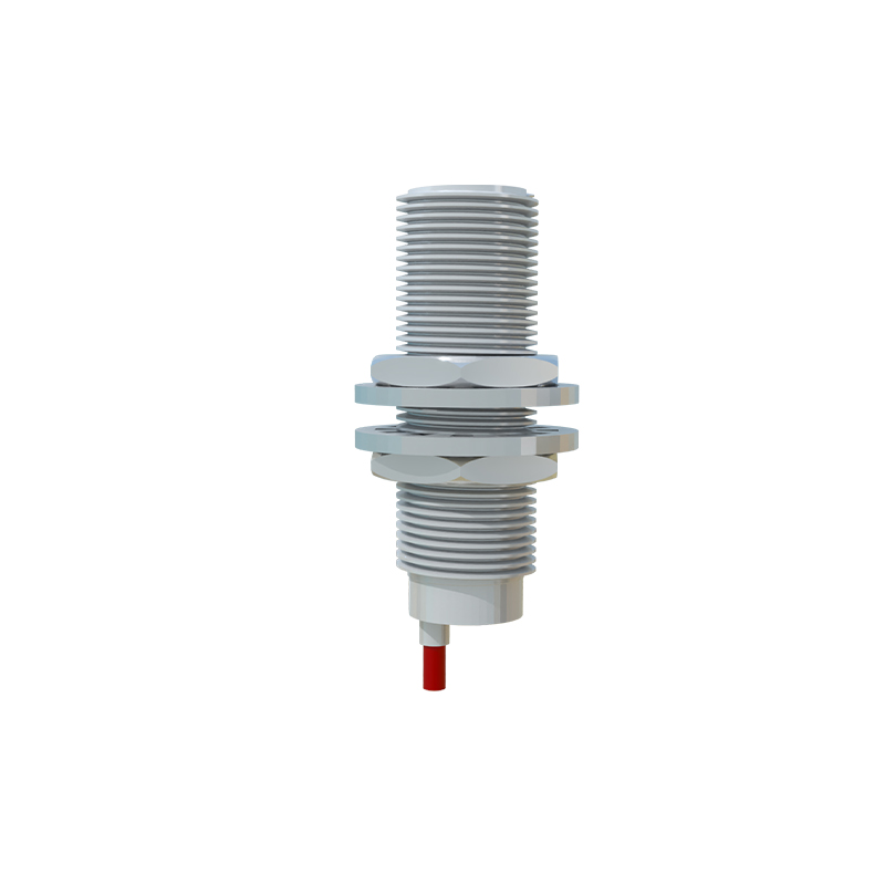
The operational principle is straightforward yet powerful. Consider an inductive proximity sensor designed to detect metallic objects. When a target enters its sensing range, the oscillation amplitude in the sensor's LC tank circuit is damped. This change is detected by the internal circuitry. In a standard digital output sensor, this triggers a solid-state switch (PNP or NPN) to change state. In a PWM-output variant, this analog damping effect is converted into a proportional digital signal. A microcontroller or dedicated ASIC within the sensor measures the amplitude shift and maps it to a specific duty cycle. For instance, a target at the maximum sensing distance might correspond to a 10% duty cycle, while a target at the minimum sensing distance (closest point) might correspond to a 90% duty cycle. The frequency of this PWM signal is typically fixed at a standard value, such as 1 kHz, 2 kHz, or 5 kHz, to ensure compatibility with receiving devices.
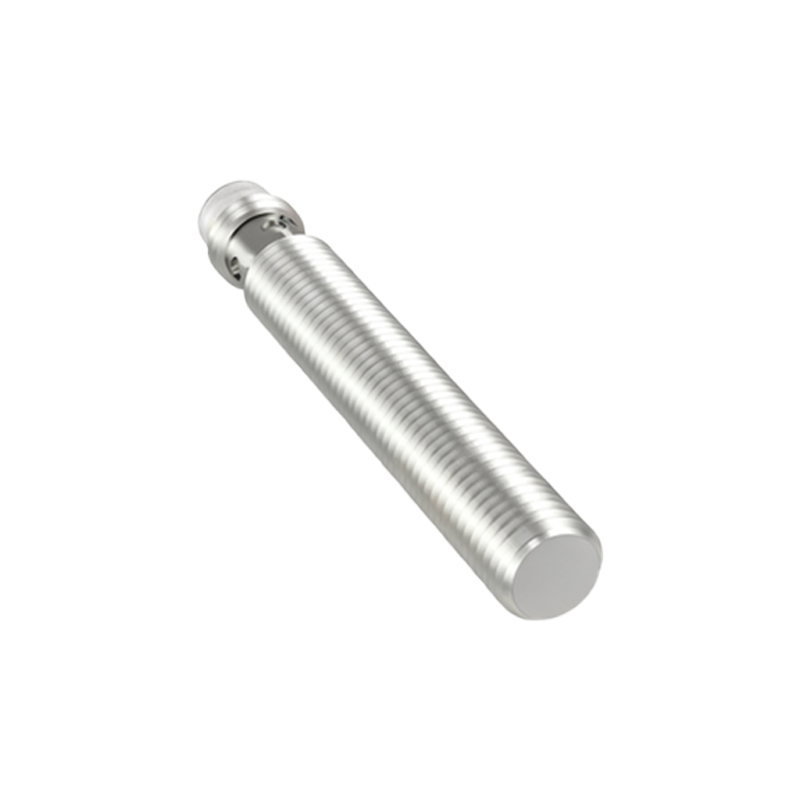
Implementing PWM output in proximity sensors offers several distinct advantages over traditional analog current (4-20 mA) or voltage (0-10 V) outputs. First, it provides inherent noise immunity. Since the signal is digital, it is less susceptible to electromagnetic interference (EMI) and voltage drops over long cable runs compared to analog signals. The receiving device only needs to distinguish between a high and low voltage state, which is more robust in electrically noisy industrial environments. Second, it allows for easy interfacing with modern digital controllers. Most microcontrollers and many PLCs have dedicated hardware or software libraries for reading PWM signals, simplifying the integration process. The digital nature of the signal also eliminates the need for an analog-to-digital converter (ADC) at the controller input, potentially reducing system cost and complexity.
However, engineers must consider specific parameters when selecting and applying PWM-output proximity sensors. The key specifications include:
1. PWM Frequency: This must be compatible with the input capabilities of the receiving controller. A frequency too high may not be readable by slower PLC inputs, while a frequency too low may cause noticeable flicker or instability in the measured value.
2. Duty Cycle Range and Linearity: The relationship between the sensed distance and the output duty cycle should be clearly defined, often specified as linear or non-linear. The datasheet will provide a characteristic curve.
3. Supply Voltage: Like all sensors, the operating voltage range (e.g., 10-30 VDC) must be adhered to.
4. Output Configuration: The output stage is typically a transistor (PNP or NPN sourcing). It is crucial to ensure the correct wiring (sourcing vs. sinking) matches the controller input module's requirements. A pull-up or pull-down resistor might be necessary depending on the configuration.
5. Load Current: The maximum current the output transistor can sink or source must not be exceeded.
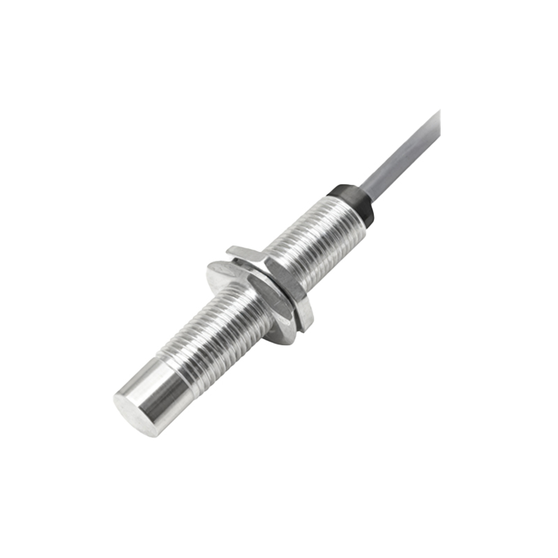
A typical wiring diagram involves connecting the sensor's brown wire (+V), blue wire (0V/GND), and black wire (PWM signal output) to the DC power supply and the controller's high-speed input. The controller then measures the ON-time of the pulses over a fixed period to calculate the duty cycle and, by referencing the sensor's calibration data, determines the corresponding distance.
In practical applications, PWM-output proximity sensors are extensively used in applications requiring precise position feedback where an analog signal is desired but with digital robustness. Examples include determining the exact position of a cylinder piston rod (by attaching a target to the rod), controlling roll diameter in winding machines, or providing fine-grained level sensing. They bridge the gap between simple presence detection and complex analog measurement systems.
In conclusion, the integration of