Proximity sensors are fundamental components in modern industrial automation, providing non-contact detection of metallic or non-metallic objects. Understanding the correct connection circuit is crucial for ensuring reliable operation, safety, and system integration. This article provides a detailed explanation of typical proximity sensor wiring diagrams, covering common types and their respective connection methodologies.
A proximity sensor typically has three or four terminals, depending on its design and functionality. The most common configurations are 3-wire DC sensors (NPN or PNP output types) and 2-wire AC/DC sensors. For a standard 3-wire DC sensor, the terminals are labeled as Brown (or +V), Blue (or 0V/Common), and Black (Output). The Brown wire connects to the positive DC supply voltage, usually ranging from 10-30 VDC. The Blue wire connects to the negative side of the power supply (0V or ground). The Black wire is the signal output line. In an NPN configuration, this output acts as a sinking switch, connecting the load to ground when activated. Conversely, in a PNP configuration, the output acts as a sourcing switch, providing positive voltage to the load upon detection.
The connection circuit must include a load, such as a programmable logic controller (PLC) input, a relay coil, or an indicator lamp. For an NPN sensor, the load is connected between the positive supply (+V) and the sensor's black output wire. When the sensor detects a target, the NPN transistor inside the sensor turns on, creating a path to ground (0V) through the blue wire. This completes the circuit, allowing current to flow from +V, through the load, through the sensor's output, to ground, thereby activating the load. For a PNP sensor, the load is connected between the sensor's black output wire and ground (0V). When activated, the PNP transistor provides a positive voltage from the brown wire to the black output wire, sending current through the load to ground.
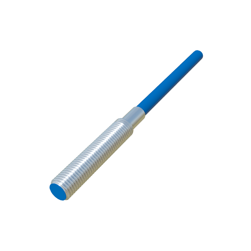
Two-wire sensors simplify wiring by having only two terminals: one for power line (often Brown) and one for load line (often Blue). They connect in series with the power supply and the load. When the sensor is off, a small leakage current flows. When activated, it allows the full load current to pass. It is critical to ensure the load's operating current falls within the sensor's specified range, and the residual leakage current when off is low enough not to accidentally activate the load.
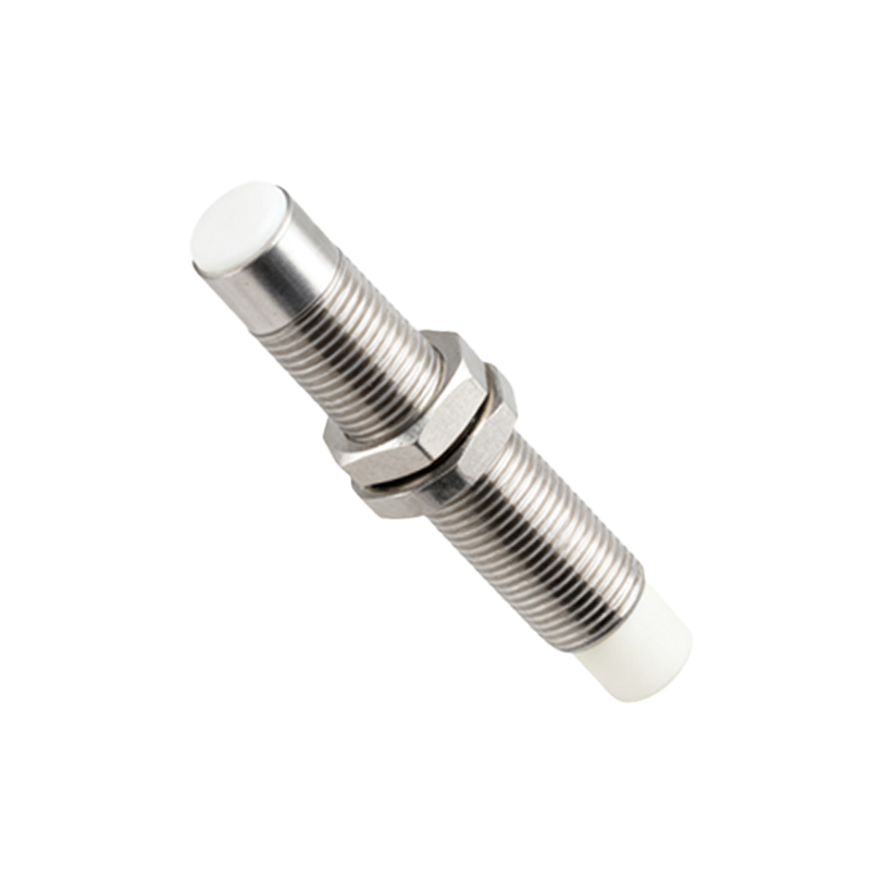
Shielded cables are highly recommended for long cable runs or in electrically noisy industrial environments to prevent electromagnetic interference (EMI) from causing false triggering. The cable shield should be grounded at only one end, typically at the control panel side, to avoid ground loops. Always refer to the manufacturer's datasheet for specific wiring colors, voltage ratings, and connection diagrams, as standards can vary.
For integrating with a PLC digital input module, the choice between NPN and PNP must match the PLC input type. Sinking PLC inputs (common to positive) require PNP sensor outputs. Sourcing PLC inputs (common to negative) require NPN sensor outputs. Incorrect matching will result in non-operation. Some sensors feature complementary outputs (both NO and NC) or analog outputs (4-20 mA, 0-10 V) for distance measurement, requiring slightly more complex circuits as per the datasheet.
A crucial step is the inclusion of protective devices. A fuse or circuit breaker in the power line is essential for overcurrent protection. For DC inductive loads like relay coils, a flyback diode (freewheeling diode) connected in reverse parallel across the load is mandatory to suppress voltage spikes generated when the circuit is opened, which could damage the sensor's solid-state output. For AC loads, a Metal Oxide Varistor (MOV) or an RC snubber network is often used across the load for surge suppression.
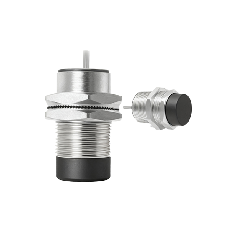
Proper installation involves maintaining the specified sensing distance, ensuring the target material and size are appropriate, and avoiding mutual interference when mounting multiple sensors closely. Always perform a functional test after connection by bringing a target within the sensing range and verifying the load's response. By meticulously following the correct circuit diagram and installation guidelines, engineers can ensure robust, maintenance-free operation of proximity sensing systems, enhancing overall machine efficiency and safety.