Capacitive proximity switches represent a cornerstone technology in modern industrial automation, offering non-contact detection for a vast array of materials. Unlike their inductive counterparts, which are limited to metals, capacitive sensors can detect solids, liquids, granules, and even powders. This versatility stems directly from their unique internal structure and operating principle. This article provides a detailed technical dissection of a standard capacitive proximity switch's architecture, explaining how each component contributes to its reliable performance.
At the heart of every capacitive proximity switch lies the sensing element, or the active surface. This is typically a metal electrode, often circular or rectangular, embedded in the sensor's face. This electrode is connected to an internal oscillator circuit. The electrode, the grounded sensor housing, and the target object together form a capacitor system. When no target is present, the oscillator operates at a specific base frequency, maintaining stability. As a target object enters the detection field, it alters the dielectric constant of the surrounding space. Even non-conductive materials have a higher dielectric constant than air. This change increases the capacitance of the system, which in turn affects the oscillator's amplitude.
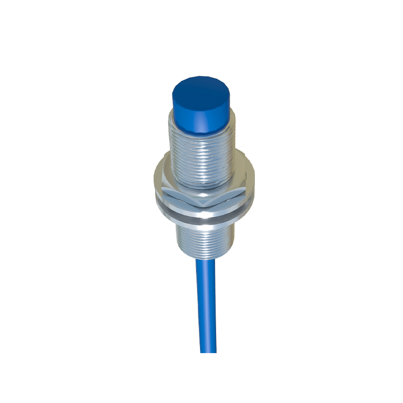
The core of the sensor's electronics is the RC oscillator circuit, sometimes implemented as a Colpitts or similar oscillator. This circuit generates a high-frequency electromagnetic field that emanates from the active electrode. The circuit is finely tuned to be sensitive to minute changes in capacitance. The amplitude of this oscillation is directly proportional to the capacitance measured at the electrode. A critical internal component is the sensitivity adjustment potentiometer. This allows engineers to calibrate the sensor's switching point, effectively setting the detection range and compensating for different material properties or background interference, such as mounting in a metal tank.
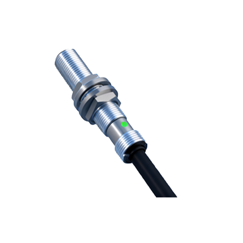
Following the oscillator is the signal evaluation stage. This circuit continuously monitors the oscillator's amplitude. Once the amplitude exceeds a pre-defined threshold—set by the sensitivity adjustment and the internal hysteresis—the evaluation circuit triggers a state change. This stage incorporates crucial filtering to reject electrical noise and rapid, insignificant fluctuations, ensuring stable switching even in electrically noisy industrial environments.
The output stage then translates this logical state change into a usable industrial signal. For a DC-powered sensor, this is typically a solid-state switch, either a PNP (sourcing) or NPN (sinking) transistor. For AC/DC universal sensors, a relay or a triac might be used. The output transistor switches the load connected to the sensor's output wire (usually the black wire). Robust overvoltage and reverse polarity protection circuits are integrated here to safeguard the electronics from common installation errors and voltage spikes.
Encasing these sensitive electronics is the housing, a critical structural component. It is usually constructed from corrosion-resistant materials like PBT (polybutylene terephthalate) or stainless steel for harsh environments. The housing provides an electrical shield, directing the sensing field forward and preventing side detection. The front face is covered by a dielectric material, often PTFE or epoxy resin. This protective barrier seals the electrode from moisture, dust, and physical damage while allowing the electric field to pass through. The choice of this material significantly impacts the sensor's performance and application suitability, especially for food-grade or chemically aggressive settings.
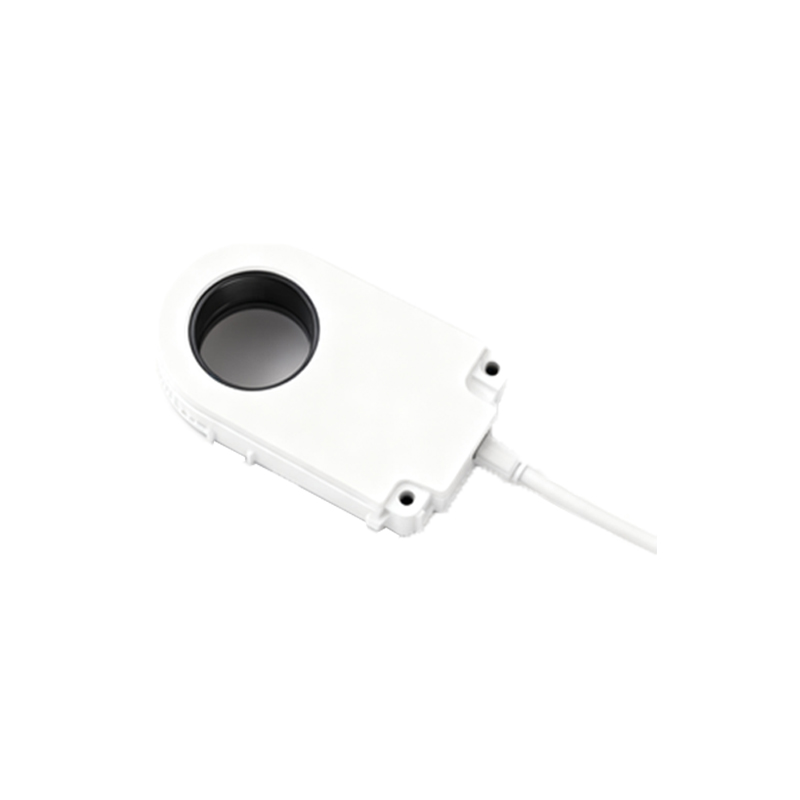
Wiring is accessed via a cable or a connector (e.g., M8, M12). Standard color coding is employed: brown for DC+ (L+ for AC), blue for DC- (N for AC), black for the switched output, and sometimes white for a complementary output or function wire. Internally, these wires are soldered to a main PCB, with strain relief mechanisms to prevent cable pull from damaging electrical connections.
Understanding this internal architecture is key to proper selection and troubleshooting. For instance, knowing the role of the sensitivity adjustment explains why a sensor might detect a container wall instead of its liquid content if not properly set. The shielded housing design clarifies why flush-mounted installation in metal is possible without false triggering. In summary, the capacitive proximity switch is an elegant synergy of electrostatic field theory, precision analog circuitry, and robust mechanical design. Its ability to reliably detect diverse materials makes it indispensable, and a deep comprehension of its structure empowers engineers to deploy it effectively across countless automation challenges.