Capacitive proximity sensors are versatile and widely used components in industrial automation, object detection, and level sensing applications. Unlike their inductive counterparts that detect only metallic objects, capacitive sensors can sense a variety of materials, including liquids, plastics, wood, and granular substances. The core of their functionality lies in their ability to detect changes in capacitance. This article delves into the schematic diagram and operational principles of a typical capacitive proximity sensor, breaking down its key electronic components and their roles.
At the heart of a capacitive proximity sensor is a capacitor formed by the sensor's active face (often a metal plate or electrode) and the target object. This forms one part of a larger capacitive system. The basic schematic diagram of such a sensor typically includes several key stages: an oscillator circuit, a demodulator/rectifier, a trigger (or Schmitt trigger), and an output switching stage (often an NPN or PNP transistor). The sensor is usually powered by a DC supply, commonly 10-30V DC.
The oscillator is the central component. In the schematic, it is often depicted as a transistor or an integrated circuit-based oscillator (like a 555 timer or a dedicated sensor IC). This circuit generates a high-frequency electromagnetic field at the sensor's active face. When no target is present, the oscillator operates at its base frequency, and the amplitude of its signal is below a set threshold. The capacitance between the sensor electrode and ground (or the sensor's internal reference) is at a specific baseline value.
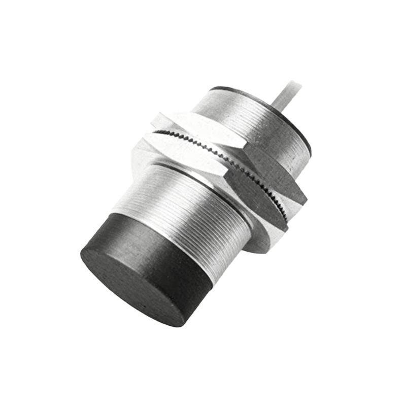
When a target object enters the sensing field, it alters the dielectric properties of the space between the sensor face and ground. Even non-conductive materials have a dielectric constant higher than air. This change increases the effective capacitance of the system. In the schematic, this is represented as a variable capacitor influencing the oscillator's tank circuit (typically consisting of an inductor and capacitors). The increased capacitance causes a change in the oscillator's characteristics—most commonly, a decrease in the oscillation amplitude or a shift in frequency.
This altered signal is then fed into the demodulator stage. In the schematic, this might be a simple diode-based peak detector or a more sophisticated integrated demodulator. Its function is to convert the high-frequency AC signal from the oscillator into a corresponding DC voltage level. This DC voltage is proportional to the amplitude of the oscillator's signal.
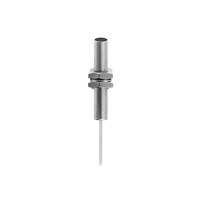
The resulting DC voltage is then passed to a trigger circuit, usually a Schmitt trigger. The Schmitt trigger, shown in the schematic as a comparator with hysteresis (often an op-amp or a dedicated comparator IC), has a predefined switching threshold. When the incoming DC voltage from the demodulator exceeds this threshold (due to the capacitance change caused by the target), the trigger's output state switches from low to high, or vice versa, depending on the design. The hysteresis prevents rapid switching due to minor fluctuations near the threshold, ensuring stable output.
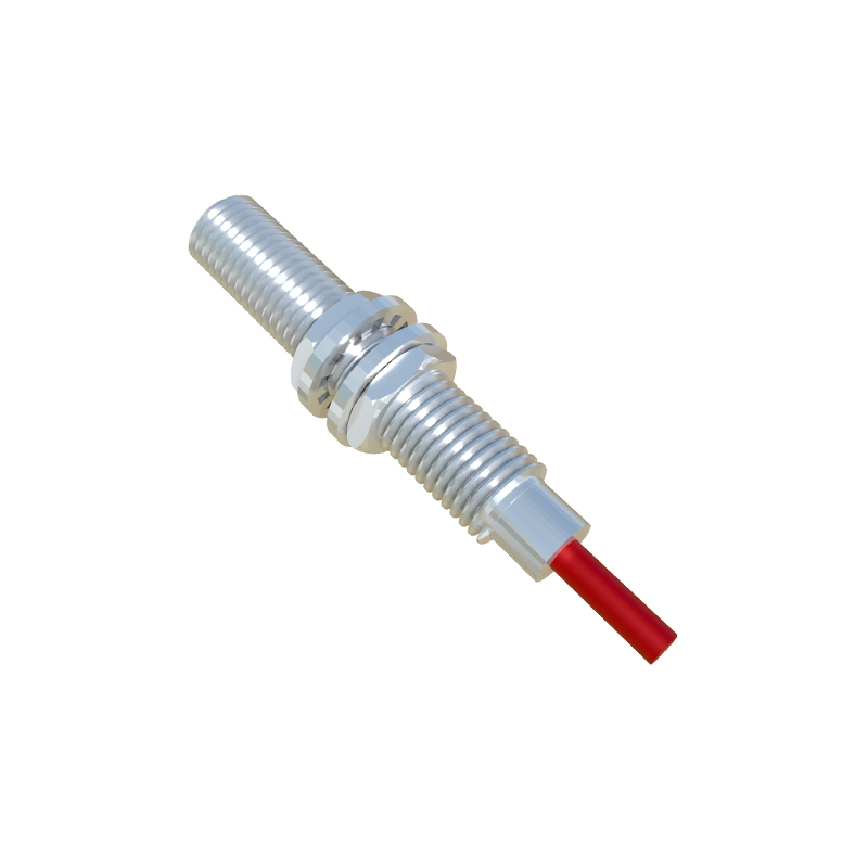
Finally, the output from the trigger drives the output switching stage. The schematic clearly shows an output transistor, configured as an open-collector (NPN) or open-emitter (PNP) switch. When activated by the trigger, this transistor saturates, allowing current to flow from the supply, through the load (e.g., a PLC input, relay, or indicator lamp), and to ground (for NPN) or from the supply (for PNP). This provides a clean digital ON/OFF signal to the connected control system. Many sensor schematics also include protective components like reverse polarity protection diodes, current-limiting resistors for the output, and filtering capacitors for power supply stabilization.
Understanding this schematic is crucial for troubleshooting. For instance, if a sensor fails to detect a target, an engineer might use an oscilloscope to check for the presence of the oscillator signal at the active face. A missing or weak signal could point to a faulty oscillator component. Similarly, checking the DC voltage before the trigger can isolate whether the issue is in the sensing/demodulation stage or the output switching stage.
In summary, the schematic diagram of a capacitive proximity sensor reveals a logical chain of signal processing: from the generation of an electromagnetic field and the detection of capacitive change, through signal conditioning and threshold comparison, to a solid-state switched output. This elegant electronic design enables reliable, contactless detection across a broad spectrum of materials, making it an indispensable tool in modern industrial systems.