Proximity sensors, particularly the widely recognized E2E series, represent a cornerstone of modern industrial automation. These non-contact detection devices are engineered to sense the presence or absence of a target object without physical touch, relying instead on electromagnetic fields, light, or sound. The "E2E" designation, a model series pioneered by Omron and now a generic term in many contexts, has become synonymous with reliable, cylindrical inductive proximity sensors. This article delves into the operational principles, key specifications, selection criteria, and practical application insights for E2E-style proximity sensors.
At the heart of the most common E2E sensor is the inductive sensing principle. The sensor generates a high-frequency oscillating electromagnetic field from its active face via a coil. When a metallic target (ferrous or non-ferrous, depending on the sensor type) enters this field, eddy currents are induced on the target's surface. This causes a change in the oscillation amplitude or frequency within the sensor's circuit. An integrated evaluation circuit detects this change and triggers a solid-state output switch, typically in the form of an NPN or PNP transistor. This entire process occurs without any physical contact, eliminating mechanical wear and enabling high-speed, long-life operation.
Key performance parameters define an E2E sensor's suitability for an application. The sensing distance, often denoted as 'Sn', is a critical specification. For a standard M18 threaded barrel sensor, this is typically 5mm or 8mm. It is crucial to note that this is a nominal value under ideal conditions; factors like target material, size, and temperature can affect the actual sensing range. The hysteresis, the difference between the switch-on and switch-off points, ensures stable operation and prevents output chattering when a target is at the borderline of the sensing range. Another vital parameter is the response frequency, measured in Hertz (Hz), which dictates how quickly the sensor can detect passing objects. For high-speed counting or sorting applications, a high response frequency is paramount.
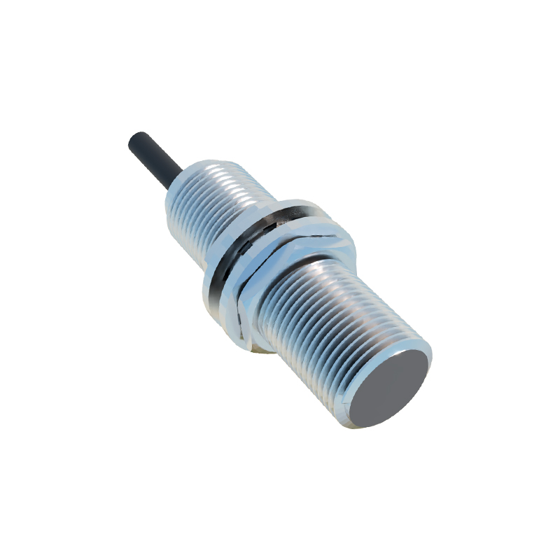
Selecting the correct E2E sensor requires a systematic approach. First, identify the target material. Standard inductive sensors detect metals, but specific types are optimized for different metals. All-metal sensors detect ferrous and non-ferrous metals at a similar range, while non-ferrous metal sensors are specifically tuned for aluminum, copper, or brass, often with a reduced sensing range for steel. Second, consider the housing style and size. The classic E2E form factor is a cylindrical, threaded metal barrel (e.g., M8, M12, M18, M30), offering robust mechanical protection and easy mounting. Shielded (flush-mountable) or unshielded (non-flush) designs are available; shielded types can be mounted flush in metal without affecting their sensing field, while unshielded types offer a longer sensing range but require a non-metallic surrounding area.
Electrical characteristics form the third selection pillar. The operating voltage range (commonly 10-30V DC) must match the control system. The output configuration—NPN (sinking) or PNP (sourcing)—must be compatible with the PLC or controller input card. The output state, normally open (NO) or normally closed (NC), defines the logic of the detection signal. Environmental ratings are equally crucial. An Ingress Protection (IP) rating of IP67 is standard for E2E sensors, indicating protection against dust ingress and temporary immersion in water, making them suitable for harsh industrial environments, including washdown areas in food and beverage plants.
In practical application, correct installation and wiring are fundamental to reliable performance. Ensure the sensor is securely mounted, paying attention to the recommended tightening torque to avoid damaging the housing. Maintain the specified lateral and axial distances between multiple sensors to prevent mutual interference. Always refer to the datasheet for the correct wiring diagram, connecting the brown wire (typically +V), blue wire (0V), and black wire (output signal) accordingly. For challenging environments with heavy electrical noise, using shielded cables and proper grounding practices is essential to prevent false triggering.
Troubleshooting common issues often involves a few checks. If a sensor fails to detect, verify the power supply, check for physical damage or buildup of contaminants on the sensing face, confirm the target is within the specified material and sensing range, and ensure the output load (e.g., PLC input) is within specifications. False triggering can often be traced to electrical noise, sensor interference, or vibration. Understanding these fundamentals empowers engineers and technicians to deploy E2E proximity sensors effectively, enhancing the reliability, efficiency, and safety of automated systems across packaging, material handling, automotive assembly, and machine tool industries.