In industrial automation and control systems, proximity switch sensors are indispensable components for non-contact detection of metallic or, in some cases, non-metallic objects. Their reliability hinges not only on selecting the correct sensor type (inductive, capacitive, or magnetic) but also on precise and correct electrical installation. A critical aspect of this installation is understanding and implementing the micro wiring diagram. This guide delves into the intricacies of proximity sensor micro wiring, providing a comprehensive overview for engineers and technicians.
The term "micro wiring diagram" typically refers to the detailed schematic showing the connection of the sensor's typically three or four wires to the control system's power supply and input module. Unlike a block diagram, it specifies wire colors, terminal designations, and the exact electrical path. Most standard DC-powered proximity switches have three wires: Brown (L+ or +V), Blue (L- or 0V), and Black (Signal Output). For a 4-wire sensor, you often find an additional White wire, which is typically a second complementary output (e.g., Normally Open and Normally Closed) or a diagnostic output.
Let's break down a standard 3-wire DC PNP (sourcing) sensor wiring. The Brown wire connects to the positive DC supply voltage (e.g., +24VDC). The Blue wire connects to the DC common or 0V. The Black wire is the signal output. In a PNP configuration, when the sensor detects a target, it switches the Black wire to supply positive voltage (+24VDC) to the PLC's digital input or the load. The PLC input's common is then connected to 0V. Conversely, for an NPN (sinking) sensor, the Brown and Blue connections remain the same for power. However, the Black output wire, when active, switches to connect the load/PLC input to 0V. Here, the PLC input's common must be connected to +24VDC. Misunderstanding PNP vs. NPN is a primary source of wiring errors.
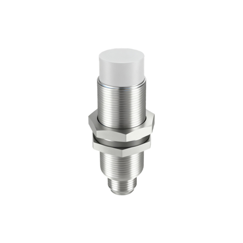
For a 4-wire DC sensor with complementary outputs (e.g., one NO and one NC), the wiring expands. Commonly, Brown (+V), Blue (0V), Black (NO output), and White (NC output). Only one output is active at a time based on the sensing state. It is crucial never to connect both outputs simultaneously to the same load or to short them, as this can damage the sensor's internal circuitry. Always consult the specific datasheet, as wire color codes, while largely standardized per IEC 60947-5-2, can vary by manufacturer.
The wiring diagram must also account for the load connection. The load (a PLC input, relay coil, or indicator lamp) is placed in series with the sensor's output wire. For a PNP sensor, the current flows from the sensor's output, through the load, and back to the power supply's 0V. For an NPN sensor, current flows from the external +V, through the load, and into the sensor's output, which then sinks it to 0V. A common mistake is wiring the load in parallel with the sensor's power supply, which will not function and may cause a short.
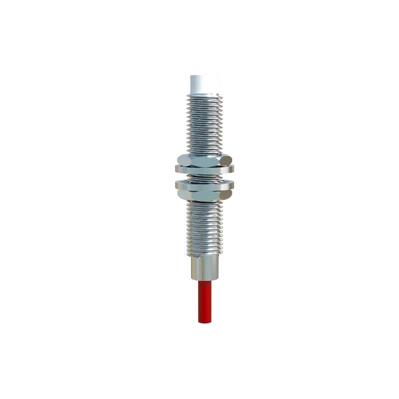
Protection components are often integrated or recommended in the micro wiring diagram. These include:
1. Reverse Polarity Protection: Modern sensors typically have built-in protection, but ensuring correct polarity is always best practice.
2. Short-Circuit Protection: Many sensors feature built-in electronic protection against output short circuits.
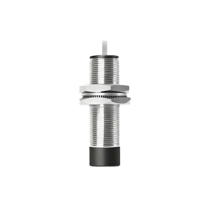
3. Surge Suppression (Snubber Diodes): When driving inductive loads like relay coils, a freewheeling diode must be connected across the load to suppress voltage spikes that could damage the sensor's output transistor. The micro diagram should indicate its orientation.
4. Fusing: A fast-acting fuse (e.g., 1A or 2A) in the positive supply line (Brown wire) is a standard safety recommendation.
For AC-powered 2-wire sensors, the wiring is simpler but has its own considerations. The two wires act as both the power leads and the switching element. They are connected in series with the AC load and the AC supply (e.g., 120VAC). A critical parameter here is the residual current or leakage current when the sensor is in the "off" state. This small current can be enough to weakly energize a highly sensitive PLC input, causing a "phantom signal." The micro wiring diagram for such scenarios often includes a bypass resistor (bleeder resistor) in parallel with the PLC input to shunt this leakage current.
Finally, adherence to the micro wiring diagram ensures electromagnetic compatibility (EMC). This includes using shielded cables for sensors in electrically noisy environments, with the shield grounded at only one end (typically the control panel