Proximity sensors are essential components in industrial automation, providing non-contact detection of metallic or non-metallic objects. Proper wiring is critical to ensure reliable operation and system safety. This guide covers common proximity sensor wiring configurations, supported by clear diagrams and step-by-step instructions.
Understanding the basic types of proximity sensors is the first step. Inductive sensors detect metallic objects, capacitive sensors detect both metallic and non-metallic materials, and ultrasonic sensors use sound waves for detection. Each type has specific wiring requirements based on its design (e.g., 2-wire, 3-wire, or 4-wire models).
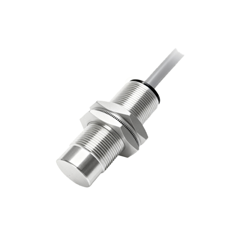
For a 2-wire AC proximity sensor, wiring is straightforward: connect one wire to the AC power source (line) and the other to the load. However, these sensors may have higher leakage current, which can affect low-power loads. Always verify compatibility with the control system.
3-wire DC sensors are widely used due to their reliability and low leakage current. They typically include brown (positive), blue (negative), and black (output) wires. In a sourcing (PNP) configuration, the black wire provides positive voltage to the load when activated. In a sinking (NPN) setup, the black wire connects to ground to complete the circuit. Diagrams illustrate these connections clearly:
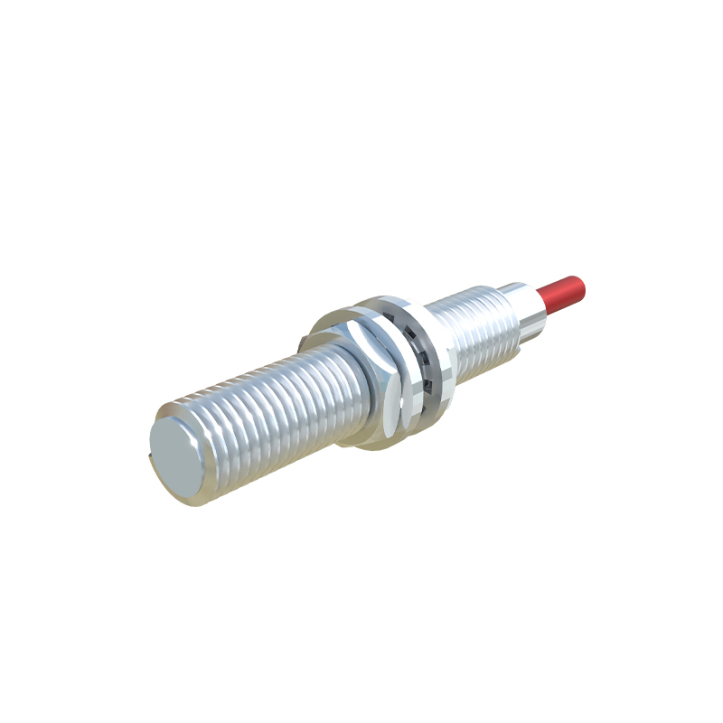
- PNP Wiring: Brown to DC+, blue to DC-, black to the load input.
- NPN Wiring: Brown to DC+, blue to DC-, black to the load ground.
4-wire sensors offer both NO (normally open) and NC (normally closed) outputs, providing flexibility for control logic. Wiring follows similar principles, with additional output wires for dual signals. Always refer to the manufacturer’s datasheet for wire color codes, as standards may vary.
Shielded cables are recommended for long runs or electrically noisy environments. Ground the shield at one end to prevent ground loops. Ensure proper separation from high-voltage lines to avoid interference.
Installation tips include mounting sensors securely, aligning targets within the sensing range, and avoiding metal-to-metal contact for inductive types. Regular testing with targets verifies functionality. For complex systems, use junction boxes or connectors to organize wiring and simplify maintenance.
Common issues like false triggering or no output often stem from incorrect wiring, voltage mismatches, or environmental factors. Double-check connections against diagrams, measure voltage levels, and inspect for physical damage.
In summary, following standardized wiring practices and referencing accurate diagrams ensures optimal sensor performance. Always prioritize safety by disconnecting power during installation and adhering to local electrical codes.