In industrial automation and precision measurement, laser sensors are indispensable tools. Their accuracy, however, is highly dependent on proper installation and alignment. One critical, yet often overlooked, parameter is the sensor's tilt angle relative to the target surface. This angle is not merely a mounting consideration; it is a fundamental variable that directly impacts measurement validity, signal integrity, and system reliability.
The core principle involves the angle of incidence—the angle at which the laser beam strikes the target. For most standard triangulation-based laser displacement sensors, the ideal and most common configuration is a perpendicular setup, where the sensor is mounted at a 0-degree tilt (90 degrees to the surface). In this orthogonal alignment, the reflected light travels back along a predictable path to the receiver, providing optimal signal strength and linearity. The sensor's specified accuracy and resolution are typically guaranteed under this condition.
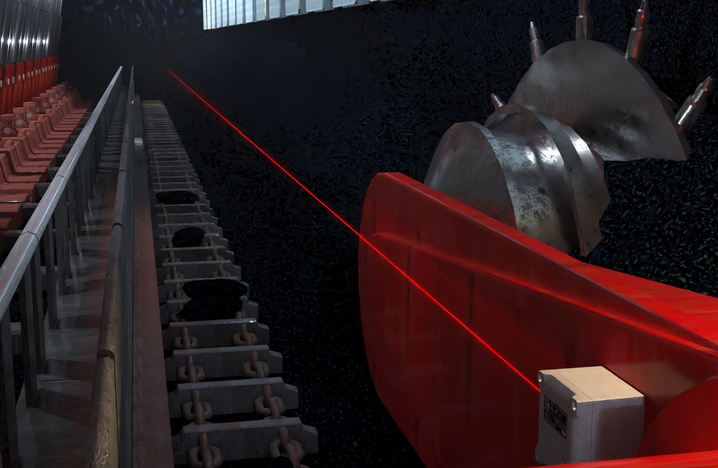
However, real-world applications frequently demand deviations from this ideal. Surfaces may be inaccessible for direct overhead mounting, or the measurement might specifically require profiling an angled feature. This is where understanding permissible tilt becomes crucial. Most sensor datasheets specify a maximum allowable tilt angle, often ranging from ±5 to ±15 degrees, depending on the model and technology (e.g., confocal or spectral interferometry sensors may have different tolerances). Exceeding this limit triggers a cascade of issues.
The primary consequence of excessive tilt is a phenomenon known as speckle noise or signal dropout. When the incident angle is too steep, a significant portion of the scattered or reflected light fails to return to the sensor's receiving lens. This results in a weakened or lost signal, causing measurement errors, instability, or complete failure. Furthermore, on specular (shiny) surfaces, an incorrect tilt can cause the main reflection to completely miss the receiver, while on rough (diffuse) surfaces, it alters the light scattering pattern, affecting spot shape and centroid calculation.

For measurements on inclined planes, a controlled, known tilt can be used intentionally. The key is compensation. If the sensor is tilted at a known angle *α*, the measured distance (*d_m*) along the sensor's axis is related to the true perpendicular distance (*d_t*) by the cosine of the angle: *d_t = d_m * cos(α)*. This trigonometric correction must be applied in the controller or software to derive the accurate geometric position. Failure to apply this math will yield a consistently skewed dataset.
Mounting and calibration practices are paramount. Use high-quality, rigid brackets to prevent vibration-induced angle drift. After physical mounting, perform a validation routine. Measure a known flat surface or a precision step gauge at multiple points, both with and against the potential tilt direction. Analyze the linearity error. For critical applications, employ an autocollimator or a digital inclinometer to verify the installed angle with high precision, as even a one-degree error can be significant over long stand-off distances.
Environmental factors also interact with tilt. Airborne particles, thermal gradients, and ambient light interference can exacerbate the negative effects of a suboptimal angle. A well-aligned sensor has a stronger signal-to-noise ratio, making it more resilient to such disturbances. Conversely, a sensor operating near its tilt limit will be more susceptible to environmental noise, leading to unreliable readings.
In conclusion, the laser sensor tilt angle is a decisive engineering parameter. It bridges theoretical specification and practical performance. Adhering to manufacturer limits, applying precise trigonometric corrections for intentional tilts, and implementing rigorous verification protocols are non-negotiable steps for ensuring measurement fidelity. Treating tilt with casual approximation is an invitation for systematic error, ultimately compromising the integrity of the entire automated process or quality inspection system. Always consult the specific sensor manual, understand the optical principle behind your device, and validate the installation under real operating conditions.