Inductive proximity switches are fundamental components in modern industrial automation, playing a critical role in non-contact object detection. As an electrical engineer, a deep understanding of their operation, selection criteria, and application nuances is essential for designing robust and reliable control systems. This article delves into the core principles and practical considerations of these ubiquitous sensors.
At its heart, an inductive proximity sensor operates on the principle of electromagnetic induction. The sensor's active face contains a coil that is part of an oscillator circuit, generating a high-frequency electromagnetic field. When a metallic object enters this field, eddy currents are induced on the object's surface. These eddy currents draw energy from the oscillator, causing a reduction in its amplitude. An integrated evaluation circuit monitors this amplitude change. Once the amplitude drop exceeds a predefined threshold—indicating the object is within the specified sensing range—the circuit triggers a switching action, changing the output state of the sensor.
The key performance characteristics of an inductive proximity switch are defined by several parameters. The sensing distance, or nominal range (Sn), is specified for a standard target, typically a square of mild steel (Fe360) with a side length equal to the sensor's diameter or the diameter of the sensing face. It is crucial to note that this range varies with different metals. Factors such as material composition, shape, and size significantly influence the effective sensing distance. For instance, the reduction factor for stainless steel is approximately 0.7-0.9, for aluminum 0.3-0.5, and for copper around 0.2-0.4. Engineers must account for these factors to avoid misapplication.
Another critical specification is the switching frequency, which defines how many on/off cycles the sensor can handle per second. High-speed applications, like counting small parts on a conveyor, require sensors with switching frequencies in the kilohertz range. The repeat accuracy, or the consistency with which the sensor detects an object at the same point, is vital for precision positioning tasks. Environmental ratings, notably the Ingress Protection (IP) code (e.g., IP67, IP69K) and temperature range, determine the sensor's suitability for harsh conditions involving dust, water, coolant, or extreme temperatures.
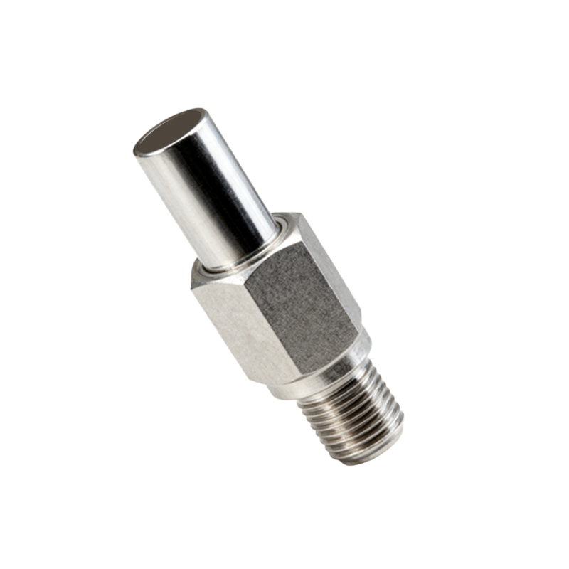
Output configurations are primarily divided into two types: two-wire and three-wire (or sometimes four-wire for dual outputs). Two-wire sensors are wired in series with the load, simplifying installation but often having a higher residual current and voltage drop. Three-wire sensors, the most common, provide separate power, ground, and signal wires, offering better performance with NPN (sinking) or PNP (sourcing) transistor outputs. The choice between NPN and PNP is dictated by the control system's PLC input card configuration—a common point of error during commissioning.
Shielded (flush-mountable) and unshielded (non-flush) designs offer different installation benefits. Shielded sensors can be mounted flush in metal without affecting their sensing field, providing excellent mechanical protection. Unshielded sensors have a longer sensing range but require a non-metallic surround to prevent interference from the mounting material.
In practical application, proper installation and wiring are paramount. Engineers must ensure adequate clearance from other metal objects to prevent false triggering. Electrical noise immunity is another major concern; using shielded cables, proper grounding, and separating sensor cables from power lines are standard best practices. For DC sensors, incorporating a flyback diode or ensuring the load has built-in protection is necessary to suppress voltage spikes from inductive loads like relays or solenoids, which can damage the sensor's output transistor.
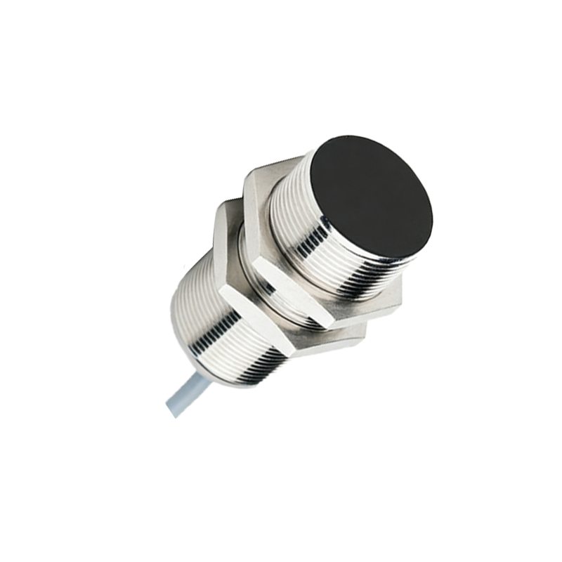
Diagnosing common issues often involves a systematic approach. Failure to detect an object can stem from an incorrect sensing distance calculation for the target material, a damaged sensor face, excessive buildup of debris, or a wiring fault. Constant activation might indicate a grounding issue, a faulty output stage, or interference from adjacent metal. Regular maintenance, including cleaning the sensing face and checking for physical damage, ensures long-term reliability.
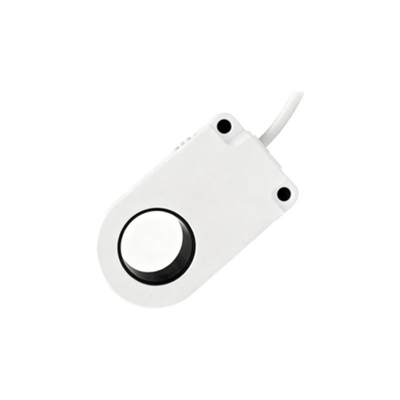
The evolution of inductive sensors continues, with trends leaning towards miniaturization, increased sensing distances, and enhanced intelligence. Modern variants incorporate IO-Link communication, allowing for parameter configuration, condition monitoring, and diagnostic data reporting directly to the controller, paving the way for predictive maintenance and Industry 4.0 integration.
For the practicing electrical engineer, selecting the right inductive proximity switch is a balance of technical specifications, environmental demands, and cost. A methodical evaluation of the target material, required sensing distance, switching speed, environmental challenges, and electrical interface will lead to an optimal choice, ensuring seamless integration and dependable operation within any automated system.