In industrial automation and control systems, the R15 series inductive proximity sensor is a cornerstone component, renowned for its reliability in detecting metallic objects without physical contact. However, its long-term accuracy and repeatability are heavily dependent on proper calibration—a process often overlooked in routine maintenance. This guide details the professional calibration procedure for the R15 proximity sensor, ensuring optimal performance in demanding environments.
The R15 sensor operates on the electromagnetic induction principle. An internal oscillator generates a high-frequency electromagnetic field from its sensing face. When a metal target enters this field, eddy currents are induced, causing a load on the oscillator. The sensor's detection circuit monitors this change, triggering a solid-state output switch. Calibration fine-tunes the sensor's sensitivity and switching points to match specific application parameters, such as the target material, size, and required sensing distance (Sn). The rated operating distance (Sn) for the R15 is typically defined for a standard mild steel target. For other metals like stainless steel, aluminum, or copper, the effective sensing distance decreases, necessitating calibration adjustments.
A systematic calibration setup is paramount. You will need: the R15 sensor mounted in its final or a representative fixture, a certified calibration target (specified material and size, usually 1" x 1" square mild steel for reference), a precision positioning jig or micrometer stage, a stable DC power supply matching the sensor's voltage rating (e.g., 10-30V DC), a digital multimeter or oscilloscope to monitor the output signal, and the sensor's datasheet for reference values. Ensure the environment is free from excessive vibration, temperature extremes, and other electromagnetic interference sources that could skew results.
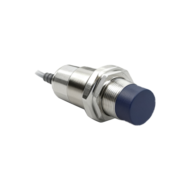
The core calibration procedure follows these steps:
1. Power and Baseline Check: Connect the sensor to its specified power supply. With no target present, verify the output state (typically "OFF" for normally open configuration). Measure the residual output voltage to ensure it is within the leakage current specification.
2. Target Approach and Switching Point Determination: Slowly advance the standard target toward the sensor's sensing face along the axial direction using the positioning jig. Precisely note the distance at which the output switches state (e.g., from OFF to ON). This is the actual "operating point." Record this distance.
3. Hysteresis Evaluation and Adjustment: After activation, slowly retract the target. Note the distance at which the output reverts to its original state. The difference between the switch-on and switch-off distances is the sensor's hysteresis. This built-in feature prevents chatter when a target is at the detection edge. Consult the datasheet to verify the measured hysteresis is within the specified range (usually 3-10% of Sn). Some advanced R15 models feature a potentiometer for sensitivity adjustment. If the operating point is too far or too close, carefully adjust this potentiometer. Clockwise rotation generally increases sensitivity (longer sensing distance), while counterclockwise decreases it. Make small adjustments and re-measure.
4. Repeatability Test: Perform at least ten consecutive approach-and-retract cycles at a consistent speed. Measure the variation in the operating point. High-quality calibration aims for minimal deviation, confirming the sensor's repeatability specification.
5. Temperature Drift Consideration (If Applicable): For critical applications, perform calibration at the operational temperature extremes to characterize and compensate for any signal drift.
Post-calibration, document all parameters: initial/final switching points, hysteresis, supply voltage, target material, and environmental conditions. This record is vital for predictive maintenance and troubleshooting. Common calibration pitfalls include using an incorrect target size/material, ignoring hysteresis, making overly aggressive sensitivity adjustments, and failing to account for the sensor's mounting (flush or non-flush), which affects the magnetic field geometry. For instance, a non-flush mounted sensor has a longer sensing range but is more susceptible to interference from surrounding metals.
Regular recalibration is recommended as part of a preventive maintenance schedule, with intervals determined by operational cycles, environmental stress, and criticality of the application. A well-calibrated R15 sensor maximizes system uptime, enhances safety by ensuring reliable detection, and contributes to consistent process quality. By adhering to this meticulous calibration protocol, engineers and technicians can ensure these robust sensors deliver their full potential in automated machinery, material handling, and robotic systems.