Laser cutting systems represent a pinnacle of precision manufacturing, and their reliable operation hinges on the flawless performance of their sensor suite. As an experienced electrical engineer in this field, I've encountered and resolved numerous sensor-related issues that can bring production to a grinding halt. This article details common failure modes, their root causes, and systematic troubleshooting approaches, providing a practical guide for fellow engineers.
The sensor ecosystem in a modern laser cutting machine is complex. Key players include capacitive height sensors for maintaining optimal nozzle-to-material distance, optical sensors for edge detection and part recognition, temperature sensors for cooling system and laser resonator monitoring, and various positional encoders and limit switches. A failure in any of these can manifest as poor cut quality, machine crashes, or unscheduled downtime.
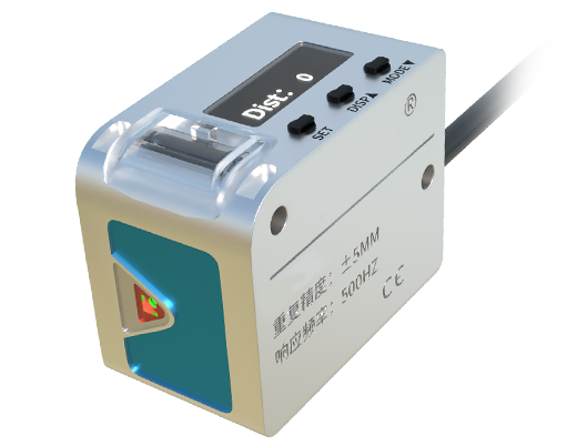
One of the most frequent issues involves the capacitive height control sensor (HCS). Symptoms include erratic torch movement during piercing, inconsistent cut quality along the path, or a complete failure to maintain standoff distance. The primary culprits are often contamination. Metal spatter, dust, and dielectric fluids can coat the sensor nozzle, altering its capacitance and providing false readings to the controller. Troubleshooting begins with a visual inspection and thorough cleaning of the sensor tip with appropriate solvents. Next, verify the sensor's calibration using the manufacturer's prescribed gauge blocks. Electrical checks should follow: measure the sensor's output signal to the CNC controller during a manual test cycle to ensure it changes predictably with distance. A flatlined signal may indicate a broken cable, a faulty connection in the quick-disconnect, or a failed sensor module itself. Environmental factors like excessive humidity or airborne conductive particles can also interfere with capacitive sensing.
Optical sensors, used for sheet edge finding or part recognition via camera systems, present another common failure point. Blurry images, failure to detect edges, or incorrect part alignment are telltale signs. The first step is always lens cleanliness; a micro-fiber cloth designed for optics is essential. Lighting is critical—check the status of integrated LEDs or external illumination rings for dimming or failure. For camera-based systems, verify the integrity of the video cable and connections. Software settings should not be overlooked; incorrect exposure time, contrast thresholds, or calibration data can mimic hardware failure. A gradual degradation in performance often points to a fading light source or lens fogging, while a sudden total failure suggests an electrical issue.
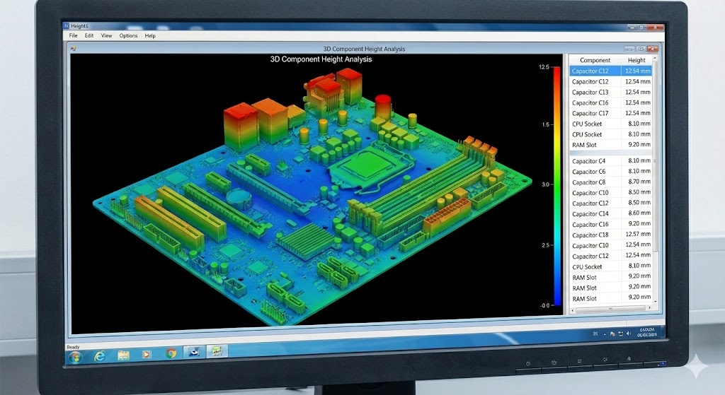
Temperature sensor failures can be insidious, leading to catastrophic damage if undetected. These sensors, typically RTDs or thermocouples, monitor laser resonator coolant, optics chillers, and linear guide temperatures. A drifting or stuck reading may cause the CNC to ignore a genuine overheating condition or trigger false alarms that stop production. Troubleshooting involves comparing the suspect sensor's reading to a known-good thermometer under stable conditions. Check the sensor's resistance or millivolt output against its data sheet. Often, the problem lies not in the sensor bead but in the extension wire, where a poor connection or break introduces error. Vibration can fatigue these fine wires over time. For critical applications, implementing a redundant sensor for cross-verification is a wise engineering practice.
Encoder and limit switch failures directly impact positional accuracy and machine safety. Erratic axis movement, loss of position (resulting in a "following error" alarm), or failure to home correctly are common indicators. For linear and rotary encoders, contamination is again a major enemy. Optical encoders can be blinded by dust or oil mist, while magnetic encoders can be affected by ferrous swarf. Inspect the read head and scale for cleanliness. Listen for unusual sounds from the motor; a failing encoder can sometimes cause audible feedback. Limit switches, often mechanical or inductive, can fail due to physical damage, misalignment, or internal contact wear. Use a multimeter to check for a change of state when the switch is actuated manually. Remember that a failed limit switch may prevent machine startup entirely due to safety interlock circuits.
A systematic diagnostic approach is paramount. Always start with the simplest solution: visual inspection and cleaning. Consult the machine's diagnostic page or PLC I/O status screen to observe the real-time sensor signal; this can quickly isolate whether the problem is mechanical, electrical, or in the signal processing chain. Document sensor values and error codes before and after the fault. Utilize manufacturer manuals for specific calibration procedures and acceptable signal ranges.
Preventive maintenance is the best defense against sensor failure. Establish a regular schedule for cleaning optical components, checking sensor mounting integrity, and verifying calibrations. Keep a log of sensor performance trends to predict end-of-life. Stock critical spare sensors, especially those with long lead times, to minimize downtime.
In conclusion, laser cutting sensor diagnostics require a blend of methodical electrical troubleshooting, mechanical understanding, and awareness of the process environment. By understanding common failure modes and adhering to a structured diagnostic workflow, engineers can swiftly restore precision and protect valuable capital equipment from prolonged damage.