In electrical and automation engineering, proximity sensor switch symbols serve as the universal language on schematic diagrams, ladder logic, and PLC layouts. Understanding these symbols is not merely an academic exercise; it is a fundamental skill for designing, troubleshooting, and maintaining modern industrial systems. These standardized icons convey critical information about a sensor's function, output type, and physical operating principle at a glance, enabling efficient communication across global engineering teams.
The foundation for most proximity sensor symbols lies in the International Electrotechnical Commission (IEC) standards, widely adopted in Europe and Asia, and the National Electrical Manufacturers Association (NEMA) or IEEE standards, more common in North America. While stylistic differences exist, the core logic remains consistent. The basic symbol for any switch, including proximity sensors, is a set of contact lines. A fundamental distinction is made between normally open (NO) and normally closed (NC) contacts. An NO symbol, representing a contact that closes when activated, is depicted as two parallel lines separated by a gap. An NC symbol, representing a contact that opens when activated, is shown as two parallel lines connected by a diagonal line, or sometimes with the contact lines touching.
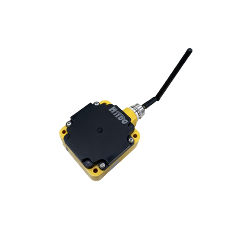
The true differentiation for proximity sensors comes from the modifier or actuator symbol placed adjacent to these contact lines. This actuator indicates the sensing method. The most common types include:
1. Inductive Proximity Sensor: The symbol features a diamond shape attached to the switch contact. This diamond represents the sensor's active face. It is universally used for sensors that detect metallic objects (ferrous and non-ferrous) through electromagnetic induction. The symbol does not specify whether the target is ferrous or non-ferrous; it simply denotes the inductive principle.
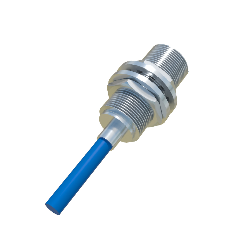
2. Capacitive Proximity Sensor: The actuator symbol is two parallel lines extending from the contact, resembling a capacitor plate. This clearly indicates the sensor operates by detecting changes in capacitance, allowing it to sense a wide variety of materials including metals, plastics, liquids, and granular substances.
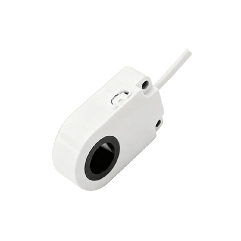
3. Ultrasonic Proximity Sensor: The symbol incorporates a stylized representation of sound waves—often curved lines radiating from a point—next to the contact. This denotes a sensor that uses ultrasonic sound pulses to measure distance to an object, effective for both solid and liquid targets.
4. Photoelectric Sensor (Optical Proximity): The symbol uses a pair of icons: a diode shape (for the emitter) and a transistor-like shape (for the receiver). For a thru-beam sensor, these are shown as two separate elements. For a retro-reflective or diffuse sensor, they are typically combined into a single symbol with both emitter and receiver in one enclosure, often with a "beam" line indicated.
5. Magnetic Proximity Sensor (Reed Switch): The symbol often includes a small horseshoe magnet shape near the contact lines. This type is specifically for detecting the presence of a permanent magnet, commonly used in cylinder position sensing.
Beyond the sensing method, the symbol must also convey the output type. This is typically indicated by the composition of the contact lines themselves within the symbol.
Digital (Switching) Output: Shown as the standard NO or NC contact symbols as described above. A "PNP" (sourcing) or "NPN" (sinking) output is not directly indicated in the symbol but is defined in the accompanying documentation or component tag.
Analog Output: Represented by a contact symbol placed next to a small, often square, wave symbol or the letters "A/O". This indicates a continuous signal output (e.g., 4-20mA, 0-10V).
Namur (Intrinsically Safe) Output: A special symbol, sometimes involving a square box with an "N" or specific shading, denotes a Namur sensor designed for hazardous areas, providing a very low-current signal to a barrier or amplifier.
A complete component designation on a diagram includes the symbol plus a alphanumeric tag, such as "B3" or "PRX1". This tag cross-references to a parts list or legend specifying the sensor's detailed part number, supply voltage, sensing range, and output configuration.
Mastering these symbols prevents costly errors. Misinterpreting an NC symbol for an NO, for instance, can lead to a dangerous failure-to-safe condition in a machine control circuit. Confusing an inductive symbol with a capacitive one could result in specifying a sensor incapable of detecting a plastic container on a packaging line. For engineers, technicians, and drafters, fluency in this symbolic language is essential. It ensures that a schematic drawn in one country can be accurately interpreted and implemented by a panel builder and maintenance crew anywhere in the world, facilitating the seamless operation of the automated systems that underpin contemporary manufacturing and processing.