Laser displacement sensors are critical tools in modern industrial automation, quality control, and research. While technical specifications provide essential data, visual representations—laser displacement sensor images—offer a unique and powerful way to comprehend their operation, applications, and results. This guide delves into the world of these images, explaining what they show and how to interpret them.
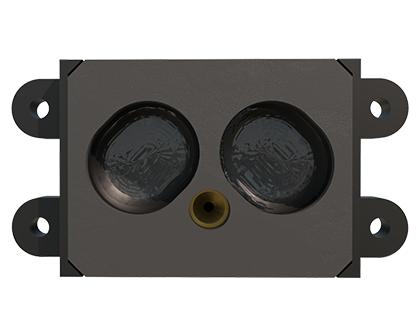
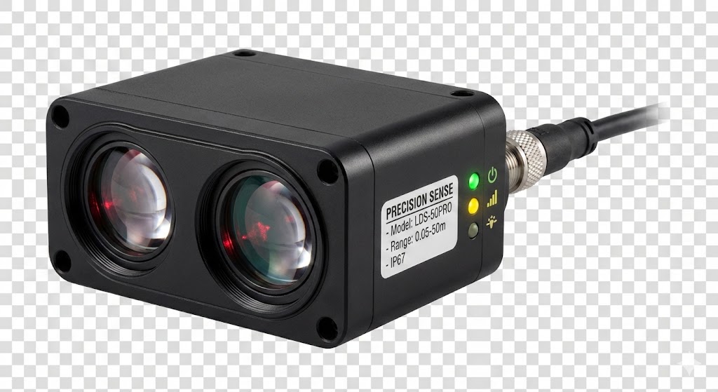
At their core, laser displacement sensors work on the principle of triangulation or time-of-flight. A common image depicts the sensor unit itself: a compact, often cylindrical or rectangular housing with a lens for emitting a focused laser beam (typically a visible red dot) and a receiving lens for capturing the reflected light. These product images help users identify form factors, mounting options, and interface connections. Seeing the physical device is the first step in understanding its integration into a system.
More informative are the schematic diagrams. These technical illustrations cut through the complexity to show the fundamental optical path. You will see the laser diode, the emitted beam striking a target surface, and the reflected light being focused onto a position-sensitive detector (PSD) or a CMOS/CCD array. The key element shown in these images is the angle of triangulation. The displacement of the light spot on the detector, caused by the target's distance change, is visually represented, making the measurement principle intuitively clear. Diagrams often include labels for the measurement range, stand-off distance, and reference points.
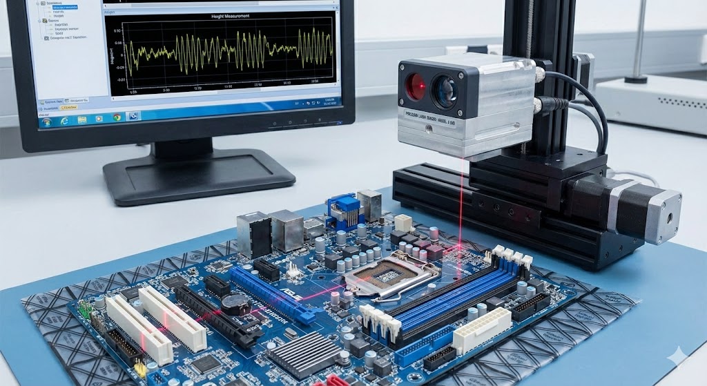
Perhaps the most valuable images are those showing the sensor in action. Application photos demonstrate real-world use cases. You might see a sensor mounted on a robotic arm, precisely measuring the gap between car body panels. Another image could show a line of sensors over a conveyor belt, scanning the height profile of pharmaceutical tablets or the thickness of rolled steel. These context-rich images answer the "how" and "where" questions, showcasing environmental factors like mounting rigidity, ambient light conditions, and target material types (e.g., shiny metal, dark rubber, translucent plastic).
The output of the sensor is another realm of imagery. While the primary output is digital data, this data is often visualized. Graphical representations include real-time waveform displays on monitor software, showing distance versus time. This is crucial for detecting vibrations, runout, or thickness variations. Another powerful image type is the 2D or 3D profile scan. By moving the sensor or the target, a series of point measurements can be combined to create a detailed cross-sectional or surface topography image. These profile images are indispensable in industries like electronics (inspecting solder paste height) or machining (verifying part flatness). They transform numerical data into an instantly recognizable visual map of the object's geometry.
When analyzing laser displacement sensor images, pay attention to key details. In application photos, note the beam's incidence angle on the target, as this affects accuracy, especially on curved or textured surfaces. Look for potential sources of error, such as secondary reflections from nearby surfaces or beam interference from other light sources. In output graphs, the scale of the axes (microns, millimeters, seconds) is critical for interpretation. A stable, flat line indicates a stationary target, while a sinusoidal wave reveals periodic motion.
Choosing the right sensor often starts with these images. A product image showing an IP67 rating symbol indicates suitability for harsh, wash-down environments. A diagram highlighting a very small spot size suggests use for measuring tiny components. An application photo with a sensor measuring a molten glass surface confirms its capability for high-temperature targets.
In conclusion, laser displacement sensor images are far more than just pictures. They are educational tools, application validators, and diagnostic aids. From simple product photos to complex profile scans, each image type serves a distinct purpose in demystifying this advanced technology. By learning to read and understand these visual resources, engineers, technicians, and procurement specialists can make more informed decisions, troubleshoot effectively, and fully leverage the precision that laser displacement sensing offers to modern manufacturing and beyond.