In industrial automation and machinery design, proximity sensors are indispensable components for non-contact detection of objects. Their reliable operation, however, is heavily dependent on a crucial, yet often overlooked, element: the mounting bracket. A poorly designed or fabricated bracket can lead to sensor misalignment, vibration-induced failures, and inaccurate readings, ultimately causing downtime. This guide provides a detailed, professional methodology for designing and fabricating a robust proximity sensor mounting bracket, suitable for various industrial environments.
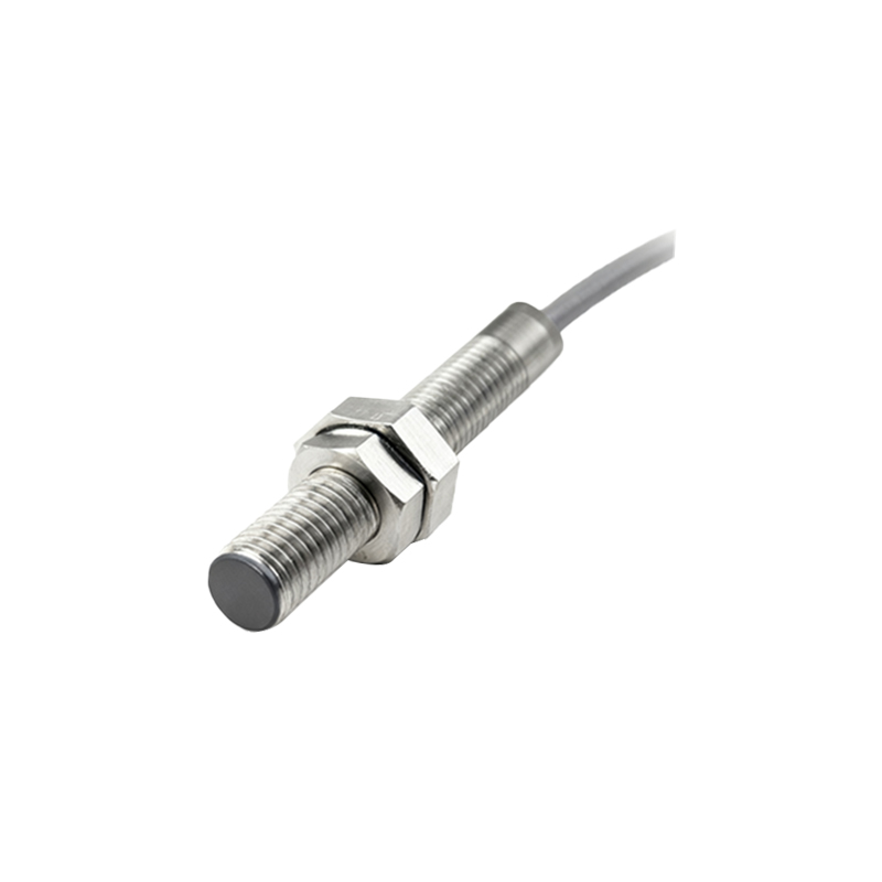
The process begins with meticulous planning and design. First, identify the specific sensor model and its datasheet. Critical dimensions include the sensor's body diameter, thread size (e.g., M8, M12, M18), sensing face profile, and required mounting clearance. Next, analyze the installation environment. Determine the target material (ferrous, non-ferrous), the required sensing distance, and any environmental challenges such as temperature extremes, coolant exposure, or significant vibration. The bracket's primary function is to position the sensor's sensing face at the precise optimal distance from the target, typically within 70-80% of the sensor's nominal range, and hold it rigidly in place.
Material selection is paramount. For most general industrial applications, cold-rolled steel (CRS) or aluminum plate is ideal. CRS offers superior strength and rigidity for high-vibration settings, while aluminum provides good strength-to-weight ratio and corrosion resistance. For washdown or corrosive environments, stainless steel (such as 304 or 316 grade) is mandatory. The typical thickness ranges from 3mm to 6mm, depending on the bracket's arm length and load.
The core fabrication involves cutting, drilling, and finishing. A detailed engineering drawing should be created specifying all dimensions. The main bracket body is cut from the chosen metal stock using a bandsaw, laser cutter, or waterjet for precision. The design often features an L-shape or a custom arm to position the sensor. The most critical machining step is drilling and tapping the sensor mounting hole. The hole must be drilled to the correct tap drill size for the sensor's thread. For an M12 sensor, for example, you would drill a 10.2mm hole and then tap it with an M12 x 1.5 tap. This thread must be perpendicular to the mounting surface to avoid angular misalignment. Use cutting fluid during tapping to ensure clean, precise threads.
A second set of holes is required to mount the bracket itself to the machine frame or subpanel. These are typically clearance holes for bolts (e.g., M6 or M8). To allow for adjustment in one plane, consider machining a slot instead of a round hole. After all holes are made, deburr all edges thoroughly using a file or deburring tool. Sharp edges are a safety hazard and can damage sensor cables. For aluminum or steel brackets (non-stainless), applying a protective finish like powder coating or zinc plating is recommended to prevent rust and enhance durability.
Installation and calibration are the final steps. Mount the bracket securely to the machine using appropriate grade fasteners and lock washers, especially in high-vibration areas. Screw the proximity sensor into the tapped hole by hand until snug, avoiding over-tightening which can damage the sensor housing. Use a gap setting tool or feeler gauges to set the exact distance between the sensor face and the target object. For adjustable brackets, loosen the locking bolts, position the sensor accurately, and then re-tighten securely. Always perform a functional test by cycling the target object and verifying the sensor's output signal with a multimeter or PLC indicator.
Common pitfalls to avoid include using materials that are too thin (leading to flex), incorrect tap size (damaging the sensor threads), poor cable management (strain on the connector), and neglecting locknuts or thread-locking adhesive on adjustment points. A well-engineered bracket is an investment in system reliability. By following these disciplined design and fabrication steps, engineers and technicians can ensure their proximity sensors deliver consistent, long-term performance, forming a solid foundation for any automated system.