As an experienced electrical engineer, I often encounter questions regarding the proper testing and maintenance of proximity sensors. These critical components are ubiquitous in industrial automation, machinery safety systems, and process control. A common diagnostic task is verifying the supply voltage using a digital multimeter (DMM). This guide provides a detailed, step-by-step procedure to safely and accurately measure the voltage of a typical 3-wire DC proximity sensor, which is the most prevalent type in industrial settings.
Understanding the Basics
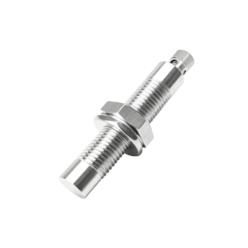
Before testing, it's crucial to understand the sensor's wiring configuration. A standard 3-wire DC proximity sensor has three distinct leads:
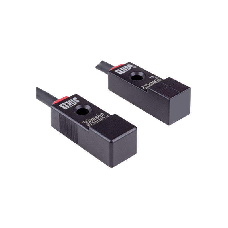
1. Brown Wire (+V): This is the positive supply voltage line. Common operating voltages are 10-30 VDC, with 24 VDC being the industry standard.
2. Blue Wire (0V or COM): This is the negative or common return line to the power supply.
3. Black Wire (Output): This is the switched output signal. When the sensor detects a target, this line either connects to +V (for a PNP, sourcing sensor) or to 0V (for an NPN, sinking sensor).

The objective of voltage testing is to confirm that the correct power is delivered between the Brown (+V) and Blue (0V) wires at the sensor's connection point.
Safety First
Always adhere to lockout/tagout (LOTO) procedures before working on any electrical circuit. Verify the circuit is de-energized before making any connections. Wear appropriate personal protective equipment (PPE). Ensure your digital multimeter is rated for the voltage you are testing and is in good working condition.
Step-by-Step Testing Procedure
Step 1: Preparation and Meter Setup
Power down the control circuit supplying the sensor. Visually inspect the sensor, cable, and connector for any signs of damage, corrosion, or loose connections. Set your digital multimeter to measure DC Voltage (V⎓). Select a voltage range higher than the expected supply (e.g., the 200V DC range for a 24V system). Insert the black test lead into the meter's COM (common) jack. Insert the red test lead into the VΩ (Volts/Ohms) jack.
Step 2: Accessing Test Points
Identify the sensor's wiring at the terminal block, connector, or directly at the sensor body. You need to access the points where the brown and blue wires are connected. If possible, use the terminal screws or a reliable test point on the connector. Do not pierce wire insulation unless absolutely necessary, as this can damage the wire and allow moisture ingress.
Step 3: Measuring Supply Voltage
Re-apply power to the control circuit. Carefully place the red multimeter probe on the terminal or wire connected to the Brown wire (+V). Place the black multimeter probe on the terminal or wire connected to the Blue wire (0V). Observe the reading on the multimeter display.
Step 4: Interpreting the Results
- Correct Voltage (e.g., ~24V DC): This indicates the power supply to the sensor is functioning correctly. If the sensor is still not operating, the issue may lie with the sensor itself, the output load, or the target.
- Voltage Too Low or Zero: This suggests a problem in the supply circuit. Potential causes include a blown fuse, a faulty power supply, a broken wire, or a high-resistance connection. Further troubleshooting of the power circuit is required.
- Voltage Too High: This could indicate a faulty power supply regulator. Excess voltage can permanently damage the sensor.
Step 5: Measuring Output Signal Voltage (Optional Diagnostic)
To further diagnose sensor operation, you can check the output voltage on the Black wire. Keep the black meter probe on the Blue wire (0V). Move the red probe to the Black output wire.
- For a PNP Sensor: The meter should read close to 0V when no target is present and close to the supply voltage (e.g., 24V) when a valid target is within the sensing range.
- For an NPN Sensor: The meter should read close to the supply voltage when no target is present and close to 0V when a target is detected.
Step 6: Power Down and Finalize
Once testing is complete, power down the circuit before disconnecting the multimeter probes. Document your findings for maintenance records.
Common Pitfalls and Tips
- Incorrect Meter Setting: Always double-check that the meter is set to DC Voltage, not AC or resistance.
- Poor