Proximity sensors are fundamental components in modern industrial automation, robotics, and countless electronic devices. Their primary function is to detect the presence or absence of an object within a specified range without any physical contact. This non-contact detection offers significant advantages, including high reliability, long operational life, and the ability to function in harsh environments. Understanding their operation is greatly enhanced through visual aids. This article delves into the core principles behind the most common types, accompanied by explanatory diagrams.
The working principle varies significantly depending on the underlying technology. The most prevalent types are Inductive, Capacitive, and Photoelectric sensors.
1. Inductive Proximity Sensors
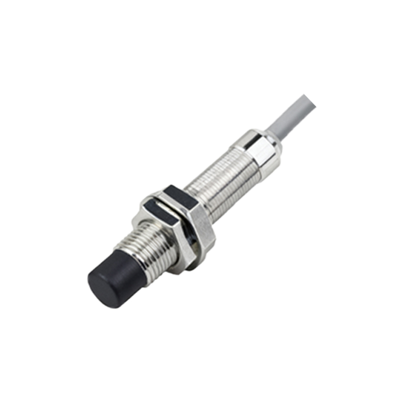
These sensors detect metallic objects, primarily ferrous metals like iron and steel. The core component is a coil wound around a ferrite core, which forms an oscillator circuit. When powered, this coil generates a high-frequency electromagnetic field at its sensing face. The diagram would show the coil, oscillator, and the emanating magnetic field lines. When a metal object enters this field, eddy currents are induced on the object's surface. These eddy currents draw energy from the sensor's oscillator, causing a reduction in the oscillation amplitude. A monitoring circuit detects this amplitude change and triggers a solid-state output switch (like an NPN or PNP transistor), signaling the object's presence. A key visual detail is that the effective sensing range is influenced by the target metal's type and size.
2. Capacitive Proximity Sensors
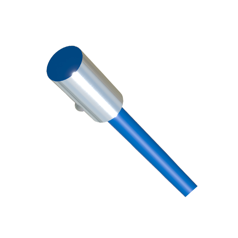
Capacitive sensors can detect both metallic and non-metallic objects, such as liquids, plastics, wood, or granules. They operate on the principle of capacitance change. The sensor's active surface acts as one plate of a capacitor, with the ground (or earth) acting as the other. The internal circuit, including an oscillator, is connected to this sensing electrode. A diagram illustrates the electric field lines projecting from the sensing face. When any material with a different dielectric constant than air enters this electrostatic field, it alters the capacitance of the system. This change increases the oscillator's amplitude. Once the amplitude reaches a specific threshold, the output circuit switches state. The sensitivity can often be adjusted to ignore certain materials (like a container) and sense the material inside it.
3. Photoelectric Sensors
These sensors use light to detect objects. They consist of a light emitter (usually an LED producing visible red, infrared, or laser light) and a receiver. There are three main configurations, best explained with diagrams:
Through-beam (Opposed): The emitter and receiver are in separate housings facing each other. An object is detected when it interrupts the light beam. This type offers the longest sensing range.
Retro-reflective: The emitter and receiver are in the same housing. They face a reflector (like a prismatic tape). The object is detected when it breaks the light beam reflected back to the receiver. A diagram shows the light path to and from the reflector.
Diffuse (Proximity): Both emitter and receiver are in the same housing. The sensor detects light reflected directly off the target object itself. The detection range depends on the object's color, reflectivity, and surface texture.
Key Operational Characteristics Illustrated:
Sensing Range (Sn): The nominal distance at which a standard target is reliably detected. Diagrams often show this as a dashed line from the sensor face.
Hysteresis: The difference between the switch-on point (as the target approaches) and the switch-off point (as it moves away). This prevents output chatter when a target is at the borderline and is a crucial feature shown in graphical timing diagrams.
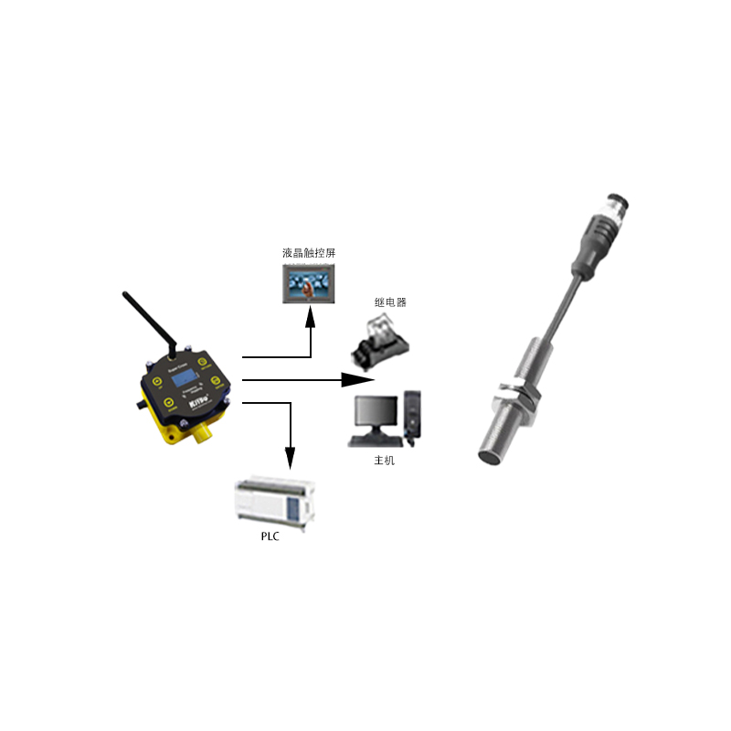
Output Types: Sinking (NPN) or Sourcing (PNP) transistor outputs are standard, depicted with their respective circuit symbols showing the flow of current to the load.
In conclusion, proximity sensors are elegantly simple in concept yet sophisticated in execution. Whether leveraging electromagnetic fields, capacitance changes, or light beams, their non-contact nature makes them indispensable. The accompanying diagrams for each type—showing magnetic/electric field lines, light paths, and internal circuitry—are essential tools for engineers to select the right sensor, understand its limitations, and integrate it effectively into a control system. Proper selection depends on the target material, required sensing distance, environmental conditions (dust, moisture), and the needed electrical output.