Proximity sensors are essential components in modern industrial automation, providing non-contact detection of metallic or non-metallic objects. Proper wiring is critical to ensure reliable operation, safety, and longevity of these sensors. This guide details the wiring configurations for common types of proximity sensors, including inductive, capacitive, and ultrasonic variants, with a focus on practical implementation in control systems.
Inductive proximity sensors, typically used for metal detection, generally feature three or four wires. A standard three-wire DC sensor includes brown (positive), blue (negative), and black (output) wires. The brown wire connects to the positive DC supply voltage (commonly 10-30 VDC), while the blue wire is linked to the DC common or ground. The black output wire interfaces with the PLC input module or relay. For a sinking (NPN) sensor, the black wire switches the load to ground when activated; for a sourcing (PNP) sensor, it switches the positive voltage. Four-wire sensors often provide both normally open (NO) and normally closed (NC) outputs, adding a white wire for the second output channel.
Capacitive proximity sensors, capable of detecting non-metallic materials, follow similar wiring principles but may include sensitivity adjustment terminals. The power connections remain consistent, but the output may be analog (0-10V or 4-20mA) for continuous measurement or digital for simple detection. Always refer to the datasheet for voltage and current ratings to prevent damage.
Wiring to a PLC involves connecting the sensor output to an input card. For a 24VDC sinking input card, use a PNP sensor; for a sourcing input card, use an NPN sensor. Ensure the PLC common is correctly tied to the sensor’s power supply common to avoid ground loops. Shielded cables are recommended for long runs in electrically noisy environments, with the shield grounded at one end to minimize interference.
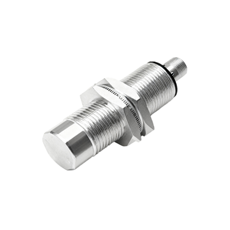
For AC-powered two-wire sensors, wiring is simpler: one wire connects to the AC hot line, and the other to the load. However, these sensors have residual leakage current, which may require a bypass resistor to prevent false triggering. Always disconnect power before wiring and use conduit or cable ducts for protection.
Key considerations include wire sizing (typically 18-22 AWG for signal lines), proper termination (ferrules for screw terminals), and adherence to local electrical codes. Label all wires clearly and document the wiring diagram for maintenance. Testing with a multimeter can verify voltage levels and output switching before full system integration.
In summary, correct proximity sensor wiring hinges on identifying the sensor type, output configuration, and power requirements. By following standardized color codes and manufacturer guidelines, engineers can ensure robust and fault-resistant installations, enhancing overall system productivity and safety. Regular inspection and compliance with ISO 13849-1 for safety-related systems further safeguard operations.