Proximity sensors are indispensable components in modern industrial automation, providing non-contact detection of metallic and non-metallic objects. Proper installation and adjustment are critical to ensuring reliable operation, maximizing sensor lifespan, and preventing costly downtime. This guide details the essential steps and best practices for installing and adjusting inductive, capacitive, and magnetic proximity sensors in industrial environments.
Pre-Installation Planning and Safety
Before handling any sensor, a thorough risk assessment and planning phase is mandatory. Always de-energize the control circuit and lock out/tag out (LOTO) the power source. Confirm the sensor type (e.g., inductive for metals, capacitive for various materials, magnetic for cylinders) is suitable for the target object and application. Verify the sensor's specifications—including sensing distance, supply voltage, output type (PNP/NPN, NO/NC), housing material, and environmental ratings (IP, NEMA)—against the operational requirements. Ensure you have the correct mounting hardware, such as brackets or nuts, and appropriate tools.
Mechanical Installation
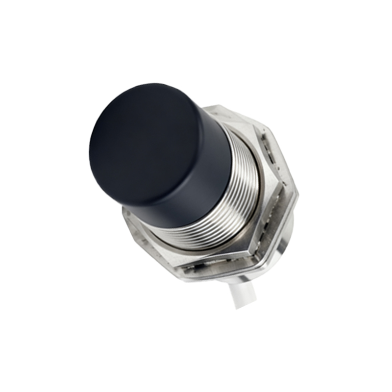
The mounting location is paramount. For inductive and capacitive sensors, ensure the sensing face is parallel to the target object's approach path. Maintain the specified nominal sensing distance (Sn), typically 0.8 times the rated operating distance, to account for factors like temperature fluctuations and supply voltage tolerance. Adhere to the manufacturer's guidelines for minimum lateral and axial distances between multiple sensors to prevent mutual interference. For barrel-style sensors, use a correctly sized wrench on the hex nut, not the sensor body, to avoid damage. Tighten to the specified torque to prevent vibration-induced loosening or housing cracks. For rectangular or block-style sensors, securely fasten them using all provided mounting holes. Always consider the target object's material, size, and possible misalignment during operation. Shielded (flush-mountable) sensors can be embedded in metal, while unshielded (non-flush) types require a clear zone around the sensing face.
Electrical Wiring and Connection
Correct electrical connection is non-negotiable. Refer to the sensor's datasheet and the connection diagram typically printed on the housing or supplied documentation. For 2-wire DC sensors, observe correct polarity. For 3-wire and 4-wire DC sensors, meticulously connect the brown wire (typically +V), blue wire (typically 0V/Common), and black wire (typically output). Connect the load (e.g., PLC input, relay coil) between the output wire and the opposite supply rail as per the PNP (sourcing) or NPN (sinking) configuration. Use shielded cables in electrically noisy environments, grounding the shield at the controller end only. Route sensor cables separately from high-voltage power lines to minimize electromagnetic interference. Secure cables with clamps to prevent strain on the connector or cable gland.
Adjustment and Calibration
After secure installation and wiring, power the system for adjustment. Most modern proximity sensors are pre-calibrated and require no potentiometer adjustment. However, fine-tuning might be necessary for challenging applications. For capacitive sensors, a sensitivity adjustment potentiometer is common. Use a non-metallic screwdriver to adjust it while presenting the target object at the desired detection point. Turn clockwise to increase sensitivity for detecting low-dielectric materials or through thin barriers; turn counterclockwise to decrease sensitivity to avoid false triggers from background materials or humidity. For adjustable-distance inductive sensors, a similar procedure applies. Never adjust the sensor to its absolute maximum range for critical applications; instead, operate within 70-80% of Sn for a reliable safety margin.
Testing and Verification
Systematic testing validates the installation. Use the actual target object, not a substitute, for testing. Move the target into the sensing field at the required speed and approach angle. Observe the sensor's output indicator LED (if present) and verify the state change at the connected controller (PLC input LED, HMI indicator). Check for proper operation at the extremes of the target's positional tolerance. Perform a "negative test" by introducing potential interfering objects (like nearby metal structures or different materials) to ensure the sensor does not actuate falsely. For critical safety-related functions, follow a documented validation protocol. Monitor the sensor's performance over several machine cycles under normal operating conditions, including typical vibration and temperature ranges.
Troubleshooting Common Issues
Persistent problems require methodical troubleshooting. If a sensor fails to detect, verify power supply voltage at the sensor terminals under load. Check for wiring errors, loose connections, or a damaged cable. Confirm the target object is within the effective sensing range and is of a suitable material and size (typically, the target should be equal to or larger than the sensor's sensing face). If false triggering occurs, investigate environmental factors: excessive dust, oil, or coolant accumulation on the sensing face; strong electromagnetic fields