In industrial automation and electrical engineering, proximity switches are indispensable components for non-contact detection. A critical, yet often overlooked, aspect of their installation and maintenance is understanding the standard wire color coding. Correct interpretation of these colors is paramount for safe, reliable, and efficient system operation. This article details the common wire color conventions for DC 2-wire, 3-wire, and 4-wire proximity sensors, aligning with international standards like IEC 60947-5-2.
For basic 2-wire DC proximity switches, the wiring is straightforward as the device acts like a switch in series with the load and power supply. There is no universal color standard, but the most prevalent convention is:

Brown Wire: Connected to the positive DC supply voltage (+V).
Blue Wire: Connected to the negative DC supply voltage (0V or common).
The load (e.g., a PLC input, relay coil) is connected between the blue wire and the negative supply. When the sensor detects a target, it closes the internal switch, allowing current to flow from brown, through the sensor, out the blue wire, through the load, and back to the power supply.
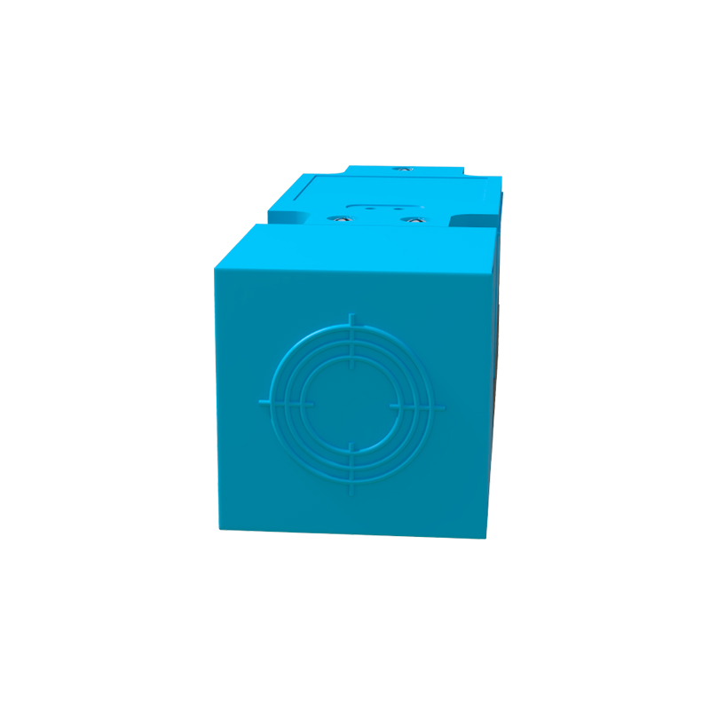
The 3-wire DC proximity sensor is the most common configuration, offering separate power and output wires. Its color code is well-standardized:
Brown Wire: Always connects to the positive DC supply voltage (+V).

Blue Wire: Always connects to the negative DC supply voltage (0V or common).
Black Wire: This is the output signal wire. Its function depends on the sensor's switching logic.
For an NPN (sinking) sensor, the black wire acts as the switched negative output. The load is connected between +V and the black wire.
For a PNP (sourcing) sensor, the black wire acts as the switched positive output. The load is connected between the black wire and 0V.
A solid-state output (transistor) in the sensor switches this black wire line. Always verify the sensor's datasheet for its specific type (PNP/NPN) and whether it is normally open (NO) or normally closed (NC).
4-wire DC proximity sensors typically provide two complementary outputs (e.g., one PNP and one NPN, or one NO and one NC). This offers greater flexibility for control logic. The standard color code extends the 3-wire scheme:
Brown Wire: Positive DC supply (+V).
Blue Wire: Negative DC supply (0V).
Black Wire: Usually the primary output signal (often PNP or a designated output 1).
White Wire: Typically the complementary or second output signal (often NPN or output 2). In some sensors, white and black wires may represent NO and NC contacts from the same switching element.
Again, consulting the manufacturer's documentation is crucial, as the white wire's function can vary (e.g., it might be a timing or control wire in specialized sensors).
For AC-powered proximity sensors (2-wire AC), the convention differs, reflecting live and neutral connections:
Brown Wire: Typically connects to the Line (L) or hot AC voltage.
Blue Wire: Typically connects to the Neutral (N) AC line.
The load is placed in series with the sensor. It is vital to note that AC sensors are functionally different from DC types and are not interchangeable.
Safety and Verification are non-negotiable. While these color codes are widely adopted, they are not absolute law. Variations exist between manufacturers, regions, and specific product lines. Relying solely on wire color without verification is a recipe for malfunction or damage. Always, without exception:
1. Refer to the sensor's nameplate and installation manual.
2. Use a multimeter to verify wire function before connection.
3. Ensure proper grounding and shielding for cables in electrically noisy environments.
Understanding proximity sensor wire color codes streamlines installation, reduces commissioning time, and minimizes costly wiring errors. By adhering to the principle of "brown for positive, blue for negative, black for output," and diligently checking documentation, engineers and technicians can ensure robust and fault-resistant automation systems. This knowledge forms a fundamental pillar of professional electrical practice.