In the realm of industrial automation and electrical engineering, proximity sensors are indispensable components for non-contact detection. A common yet crucial question that arises during installation, maintenance, or procurement is: what is the wire of a proximity sensor called? The answer is not a single term but depends on its function and construction. Primarily, this assembly is referred to as the sensor cable or proximity sensor cable. However, to be precise, it is often called the integrated cable or the connector cable assembly. Unlike devices with separate connector ports, many proximity sensors come with a permanently attached cable, making this assembly a key part of the unit.
Delving deeper, the wires within this cable are typically called lead wires or conductors. Their naming convention is standardized by color codes and international standards, which define their electrical functions. For a standard 3-wire DC proximity sensor (the most common type), the wires are:
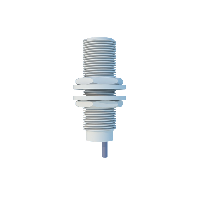
Brown Wire: This is the positive supply line, often labeled as V+ or L+. It connects to the positive terminal of the DC power source.
Blue Wire: This is the negative supply line or 0V line, labeled as V- or L-. It connects to the negative terminal or ground of the DC power source.
Black Wire: This is the output signal wire. It carries the switching signal (typically a load) from the sensor to the programmable logic controller (PLC), relay, or other control device. In some configurations, a white wire might be used as a second output or a complementary signal.
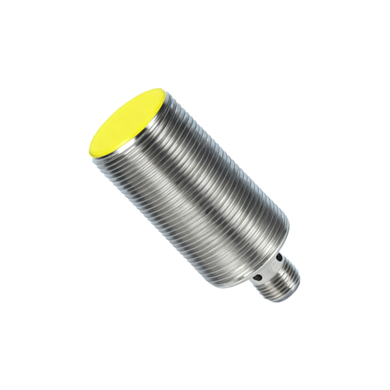
For 4-wire sensors, which often include two output signals (e.g., one normally open and one normally closed), you will find an additional wire, usually white. The consistent use of these color codes (brown, blue, black, white) as per IEC 60947-5-2 standards is critical for safe and correct wiring, preventing short circuits or device damage.
The terminology extends further based on the cable's end point. If the cable terminates in a plug, it is commonly called a pigtail cable or pre-wired cable. When the cable ends in individual stripped and tinned conductors, it is simply referred to as a cable with flying leads. In environments requiring frequent sensor replacement, a quick-disconnect cable system is used, where the sensor has a standardized connector (like M8 or M12), and the cable is called an M12 cable assembly or M8 connector cable. This allows for easy disconnection without rewiring.
The construction of the cable itself is also a point of specification. Key terms include:
Shielded Cable: Contains a braided or foil shield (often called the drain wire) to protect against electromagnetic interference (EMI), crucial in environments with motors or variable frequency drives.
Jacket Material: Specified as PVC, PUR, or TPE, indicating resistance to oils, chemicals, or temperature extremes.
Conductor Gauge: Refers to the thickness of the individual wires, commonly AWG 18 or AWG 20.
Understanding this terminology is vital for engineers and technicians. Specifying the correct "wire" or cable ensures system reliability. For instance, ordering a replacement part requires knowing if you need a 2-meter PVC-jacketed, shielded M12 to flying leads cable or simply a sensor with an integrated 4-wire cable. Misidentification can lead to procurement errors, installation delays, and operational failures.
In summary, while colloquially called the "wire," the correct technical references are proximity sensor cable, integrated cable assembly, or lead wire set, defined further by connector type, wire color codes, and jacket specifications. Mastery of this vocabulary enhances communication in datasheets, purchase orders, and maintenance logs, ensuring precision in the complex and interconnected world of industrial sensing and control.