In industrial automation and control systems, proximity sensors are indispensable components, providing non-contact detection of metallic and sometimes non-metallic objects. Their reliability is paramount for continuous operation. However, a frequent and frustrating issue encountered by maintenance engineers and system designers is the premature failure or "burning out" of these sensors. This phenomenon goes beyond simple wear and tear and often points to specific electrical, environmental, or application-related stressors. Understanding the root causes is crucial for prevention and ensuring system uptime.
A primary culprit behind proximity sensor burnout is electrical overstress. This encompasses several specific scenarios. Voltage spikes and transients on the power supply lines are a major threat. These surges can originate from the switching of large inductive loads nearby, such as motors, solenoids, or contactors. When these loads de-energize, they can generate high-voltage back-EMF pulses that travel back along the power lines, exceeding the sensor's maximum rated voltage and damaging its internal solid-state circuitry, typically the output switching transistor or oscillator components. Even brief spikes can cause cumulative damage leading to failure.
Incorrect power supply voltage is another fundamental yet common error. Applying a voltage higher than the sensor's specification, for instance, connecting a 12-24VDC sensor to a 48VDC source, will cause excessive current flow and overheating, rapidly destroying the device. Conversely, under-voltage might not cause immediate burnout but can lead to unstable operation and increased stress on components. Furthermore, issues with wiring, such as short circuits in the load circuit or incorrect polarity for DC sensors, can force excessive current through the output stage, leading to thermal overload and failure.
The second major category of causes relates to improper load handling. Every proximity sensor has a specified maximum load current. Exceeding this rating, either by connecting a load that draws too much current or by a direct short circuit, causes the sensor's output transistor to operate outside its safe operating area. This generates excessive heat. While many sensors incorporate short-circuit protection, this protection is often based on thermal limits. Repeated or prolonged overload conditions will cause the protection circuit to cycle or eventually fail, resulting in the thermal destruction of the output component. Inductive loads like relay coils or solenoid valves present a special challenge. Without proper suppression (using flyback diodes, RC networks, or metal-oxide varistors), the voltage spike generated when the inductive load is switched off can avalanche back into the sensor's output, causing breakdown.
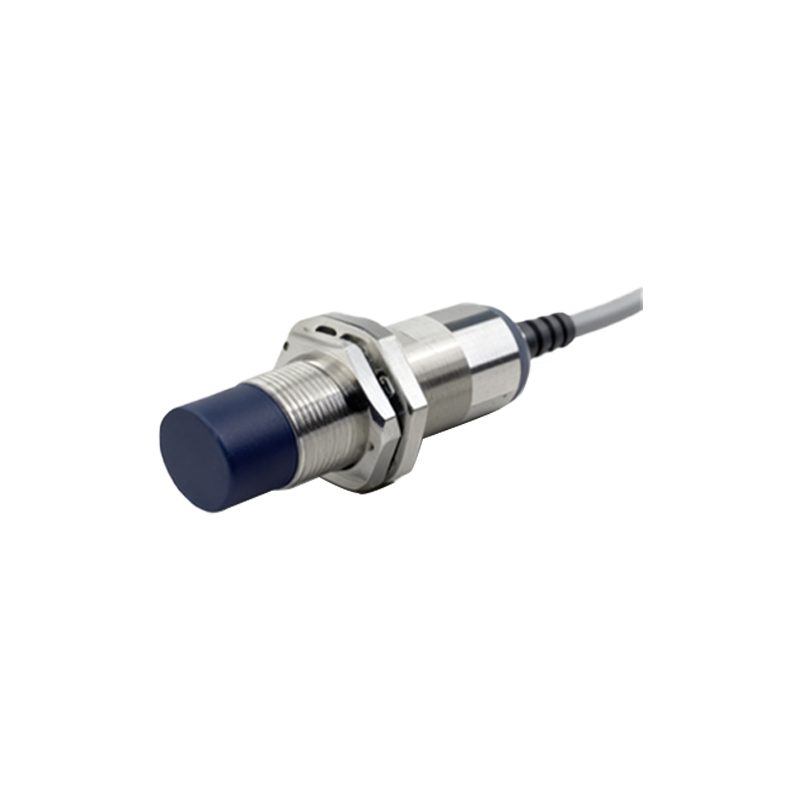
Environmental factors play a significant and sometimes underestimated role. Excessive ambient temperature is a silent killer. Operating a sensor near its upper-temperature limit, or in an enclosure without adequate heat dissipation, reduces its ability to cool itself. The internal heat generated during normal operation cannot dissipate, causing component temperatures to rise beyond design limits. Contamination is another environmental hazard. Conductive dust, metallic chips, or corrosive chemicals can bridge connections on the sensor's face or housing, creating leakage paths or short circuits. For instance, in machining applications, conductive coolant mixed with metal swarf can accumulate on a sensor, potentially causing erratic behavior or current leakage that leads to overheating.
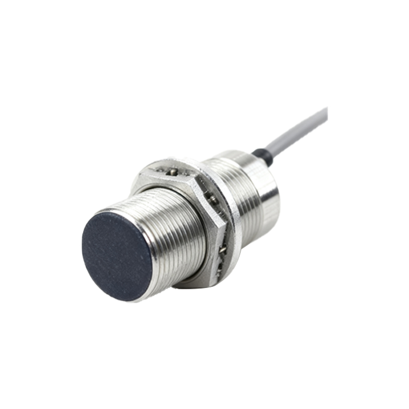
Physical installation and application mistakes also contribute to failures. Mechanical stress from vibration or shock can crack internal solder joints or components. Using a sensor in a manner inconsistent with its design—for example, using a standard inductive sensor to detect non-ferrous metals at its maximum range, which requires higher oscillator power—can strain the internal oscillator circuit. Additionally, sensor mounting in metallic surroundings without maintaining the required flush-mount or non-flush-mount distances can cause the sensing field to interact with the mounting metal, leading to increased power draw and heating.
Finally, the inherent limitations of component selection and design for cost-sensitive markets can be a factor. Manufacturers may use components rated with minimal safety margins to meet price points. While these sensors function correctly under ideal conditions, they have less resilience to the real-world electrical noise, voltage fluctuations, and thermal cycles found in harsh industrial environments. This makes them more susceptible to failure from events that a more robustly designed sensor might withstand.
Prevention is always more cost-effective than repair. To mitigate burnout risks, engineers should: ensure a stable, clean power supply, possibly using line filters or surge suppressors; strictly adhere to voltage and current ratings, derating loads where possible; always use protective devices for inductive loads; select sensors with an appropriate IP rating and temperature range for the environment; follow mounting guidelines precisely; and consider investing in higher-grade sensors with wider operating margins for critical applications. A systematic approach to installation, commissioning, and maintenance, focusing on electrical integrity and environmental protection, will dramatically extend the service life of proximity sensors and enhance overall system reliability.