Laser speed sensors represent a critical technology in modern industrial automation, transportation monitoring, and scientific research. These devices measure the velocity of moving objects with high precision by utilizing the principles of laser Doppler effect or time-of-flight calculations. To fully grasp how these sensors operate, examining their schematic diagram is essential. This diagram visually breaks down the key components and their interconnections, providing a clear roadmap of the sensor's functionality.
At the heart of a typical laser speed sensor schematic, you will find a laser diode serving as the light source. This diode emits a coherent, focused beam of light toward the target object. The schematic clearly shows the laser diode connected to a driver circuit, which ensures stable and consistent output. Adjacent to this, optical components like lenses and beam splitters are depicted, directing the laser beam precisely.
The reflected or scattered light from the moving object is captured by a photodetector, another crucial element in the diagram. This component converts the incoming light signals into electrical signals. In schematics based on the Doppler effect, the photodetector is often linked to a signal processing unit that analyzes frequency shifts between the emitted and reflected light. These shifts correlate directly with the object's speed. For time-of-flight designs, the diagram illustrates precise timing circuits that measure the delay between laser pulse emission and reception.
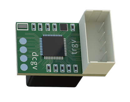
Signal conditioning circuits are prominently featured in the schematic, showing amplifiers and filters that enhance the weak electrical signals from the photodetector. These conditioned signals are then fed into a microcontroller or digital signal processor (DSP), which performs the necessary calculations to determine speed. The output stage, displayed as part of the schematic, may include interfaces like analog voltage outputs, digital communication ports (e.g., RS-485 or Ethernet), or display modules for real-time readings.
Power supply sections within the diagram highlight voltage regulators and protection circuits, ensuring reliable operation under varying industrial conditions. Additionally, many schematics incorporate feedback loops or calibration modules to maintain accuracy over time. By studying these interconnected components, engineers and technicians can troubleshoot issues, optimize performance, or integrate the sensor into larger systems.
Applications of laser speed sensors span numerous fields. In manufacturing, they monitor conveyor belt speeds or robotic arm movements. Traffic management systems use them for vehicle speed detection, while scientific instruments employ them in fluid dynamics studies. The schematic diagram serves as a universal reference across these applications, enabling consistent implementation and innovation.
Understanding the schematic is not merely about recognizing symbols; it involves appreciating how each part contributes to the sensor's reliability and precision. For instance, the choice of laser wavelength affects performance in different environments, and the photodetector's sensitivity influences measurement range. These details are often annotated in comprehensive schematics, providing deeper insights into design considerations.
In summary, the schematic diagram of a laser speed sensor is a vital tool for comprehending its operation. It bridges theoretical principles with practical engineering, showcasing the seamless integration of optics, electronics, and computing. Whether for educational purposes or professional development, analyzing this diagram enhances one's ability to leverage laser sensing technology effectively in diverse scenarios.