In the realm of industrial automation and control systems, proximity sensors are indispensable components for non-contact object detection. Among the various types, 3-wire DC sensors utilizing PNP and NPN output configurations are the most prevalent. Understanding the fundamental difference between PNP and NPN proximity sensors is crucial for engineers, technicians, and system integrators to ensure correct wiring, compatibility with controllers, and overall system reliability. This article delves into the core distinctions, operational principles, and practical selection criteria.
At the heart of the difference lies the type of semiconductor switching device used and the resulting circuit configuration. The terms PNP and NPN refer to the type of bipolar junction transistor (BJT) employed in the sensor's output stage. This internal transistor acts as a solid-state switch to control the flow of current to the load (e.g., a PLC input, relay, or indicator lamp).
A PNP proximity sensor is often described as "sourcing" output. In its normal state (no target detected), the output transistor is off. When a target enters the sensing range, the sensor activates its internal circuit, turning the PNP transistor ON. This action connects the output wire to the positive supply voltage (+V). Current now sources from the sensor's output terminal, flows through the load, and completes the circuit to the common negative (0V) or ground. Essentially, the PNP sensor provides the positive voltage to the load when activated. The typical wiring involves connecting the brown wire (+V), blue wire (0V), and the black wire (output) to the load, which is then connected to common negative.
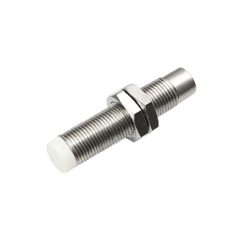
Conversely, an NPN proximity sensor is categorized as a "sinking" output. In its idle state, the output is off. Upon detecting a target, the internal NPN transistor switches ON. This action connects the output wire to the negative supply voltage (0V). Current flows from the positive supply, through the load, and sinks into the sensor's output terminal to ground. The NPN sensor provides a path to ground for the load when activated. Standard wiring connects the brown wire (+V), blue wire (0V), and the black wire (output). The load is connected between the positive supply and the sensor's output black wire.
The choice between PNP and NPN is largely dictated by regional conventions and the type of control system input module. A general observation is that PNP (sourcing) sensors are predominantly used with sinking input modules on Programmable Logic Controllers (PLCs) in many parts of the world, including Europe and Asia. Sinking input modules have their input point connected internally to +V, expecting the sensor to connect it to 0V to indicate an "ON" state—a role perfectly fulfilled by a PNP sensor. On the other hand, NPN (sinking) sensors are commonly paired with sourcing input modules, which are more traditional in some regions like Japan and are found in various applications. A sourcing input module has its input point connected internally to 0V, expecting the sensor to provide +V, which is what an NPN sensor does when it switches and provides a path to ground.
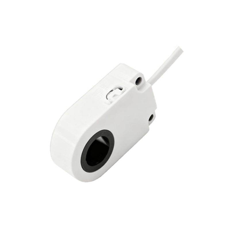
From a practical electrical perspective, both types are functionally equivalent in terms of switching capability. However, mixing them incorrectly can lead to a non-functional circuit or, in worst-case scenarios, potential damage. A simple rule for compatibility is: The sensor output type and the PLC input type should be opposites. A sourcing output (PNP) works with a sinking input, and a sinking output (NPN) works with a sourcing input.
Several key factors influence the selection process beyond convention:
1. PLC/Controller Specification: Always consult the controller's manual first. The input circuit design dictates whether you need a PNP or NPN sensor.
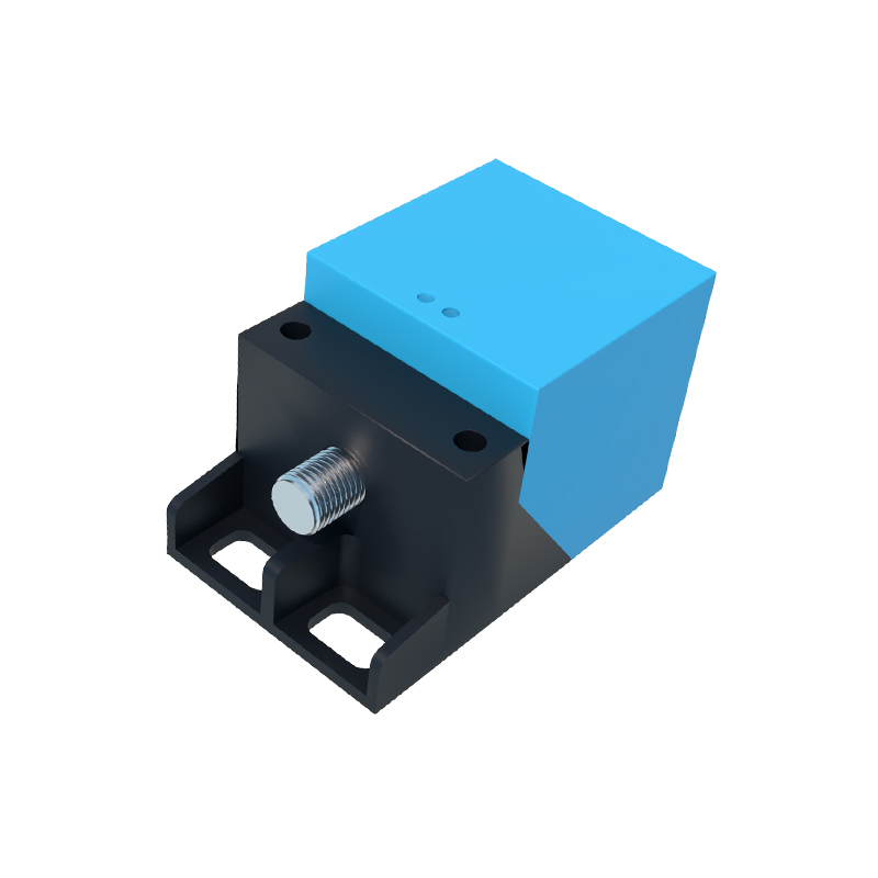
2. Wiring and Safety Considerations: In some safety-critical or fail-safe circuit designs, one configuration might be preferred to achieve a "fail-safe" state (e.g., a broken wire simulating an "off" signal). NPN configurations are sometimes used in applications where it is desirable to have the load de-energized in a fault condition.
3. Multi-sensor Networking: When connecting multiple sensors to a single input, consistency in output type (all PNP or all NPN) is typically required, often achieved through parallel or series connections following specific rules.
4. Availability and Standardization: Many facilities standardize on one type to simplify maintenance, spare parts inventory, and technician training.
In summary, the operational difference is clear: PNP sensors switch the positive voltage line, while NPN sensors switch the negative or ground line. This fundamental electrical distinction directly impacts how the sensor