Wiring a 220V AC proximity sensor correctly is a fundamental task for industrial electricians, automation engineers, and maintenance technicians. These robust sensors, crucial for object detection, position control, and safety interlocks, operate on a standard industrial voltage. Incorrect wiring can lead to immediate sensor failure, damage to connected machinery like PLCs, or create serious safety hazards. This guide provides a clear, professional procedure for safely and effectively connecting a 2-wire or 3-wire AC proximity sensor to a 220V power supply.
Before handling any electrical components, the paramount rule is safety. Always ensure the main power supply is locked out and tagged out (LOTO). Verify the absence of voltage at the installation point using a properly rated multimeter or voltage tester. Wear appropriate personal protective equipment (PPE), including safety glasses and insulated gloves. Confirm the sensor's specifications on its nameplate: it must be rated for 220V AC (often listed as 90-250V AC) and the correct type (inductive, capacitive). Also, note the required load current and ensure your power supply and wiring can handle it.
The wiring process differs between 2-wire and 3-wire AC sensors. For a standard 3-wire AC proximity sensor, you will typically find three colored wires: Brown, Blue, and Black (or sometimes Brown, Blue, and White). The international standard (IEC) for AC sensors is: Brown for the live or phase conductor (L1), Blue for the neutral conductor (N), and Black (or the third color) for the load or switching output wire. The sensor itself is powered between Brown and Blue. The Black wire is the output; when the sensor detects a target, it closes a solid-state switch between the Black wire and the live (Brown) wire, allowing current to flow to the load.
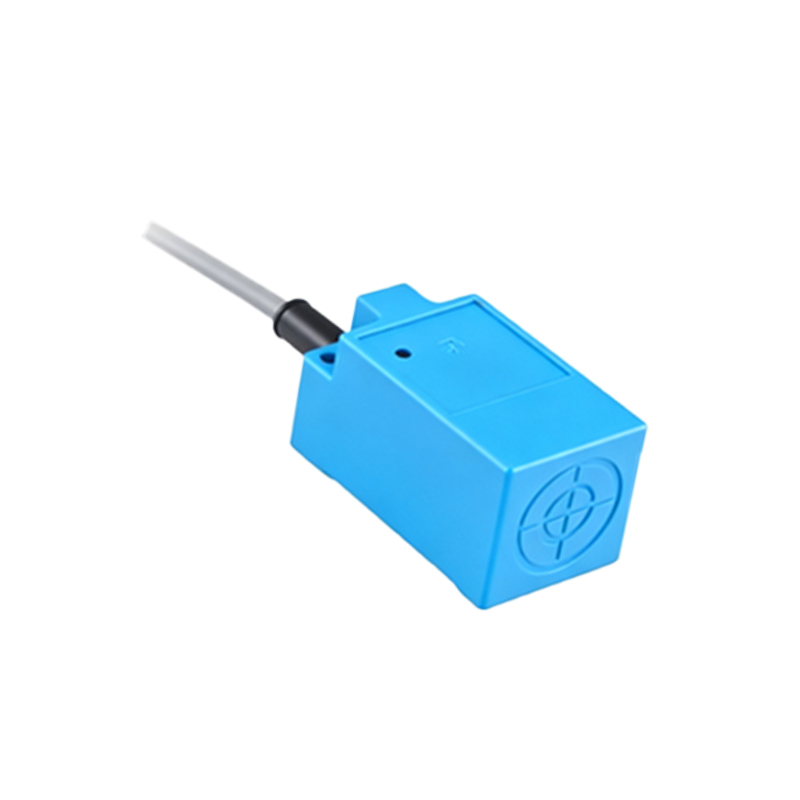
Here is the step-by-step wiring procedure for a 3-wire sensor:
1. Prepare the Circuit: From your 220V AC power source, you will have a Line (Hot) and a Neutral conductor. Run these conductors to the sensor's intended location in a suitable conduit.
2. Connect Sensor Power: Connect the 220V AC Line (Hot) wire to the sensor's Brown wire. Connect the 220V AC Neutral wire to the sensor's Blue wire. These connections provide operating power to the sensor's internal electronics.
3. Connect the Load: The load (e.g., a PLC input module, a relay coil, or an indicator lamp) must be connected in series with the sensor's output. Connect one terminal of your load device to the sensor's Black output wire.
4. Complete the Load Circuit: Connect the other terminal of your load device back to the 220V AC Line (Hot) source. This creates a complete circuit: Hot -> Sensor (internal switch via Brown/Black) -> Load -> back to Hot. Important: Some sensor datasheets specify the load should be connected between the Black wire and Neutral. Always consult the manufacturer's documentation, as this is less common but possible.
5. Grounding: Ensure the metal housing of the sensor is properly connected to the facility's protective earth (PE) ground using a green/yellow wire, if the sensor has a grounding terminal.
For a 2-wire AC proximity sensor, the wiring is simpler as the sensor acts like a switch in series with the power line and the load. The two wires are not polarized. You connect one wire to the 220V AC Line, and the other wire to one side of your load. The other side of the load is then connected to the 220V AC Neutral. The sensor passes current to power itself and the load when activated.
After all connections are made and double-checked for tightness and correctness, you can proceed to testing. Restore power cautiously. Observe the sensor's LED indicator (if equipped). It should illuminate when powered and may change state (e.g., turn off or blink) when a target enters its sensing range. Use a multimeter to verify the voltage at the load terminals. When the sensor is inactive (no target), there should be minimal voltage across the load. When activated, you should measure close to the full supply voltage across the load, indicating the switch is closed and current can flow.
Common pitfalls to avoid include confusing AC and DC sensor wiring (they are not interchangeable), over-tightening terminal screws and damaging wire strands, neglecting to install a separate fuse in the circuit for protection, and failing to consider voltage drops in long wire runs. For sensors controlling inductive loads like relay coils, it is highly recommended to use a surge suppressor (like an RC network or metal-oxide varistor) across the load to protect