Proximity sensors are indispensable components in modern industrial automation, providing non-contact detection of objects. Their circuit design is fundamental to achieving reliable, accurate, and robust operation in harsh environments. This article delves into the core circuit topologies for inductive, capacitive, and photoelectric proximity sensors, outlining key design considerations and implementation strategies.
The heart of an inductive proximity sensor is an LC oscillator circuit. A coil (the sensor head) forms the inductor (L), and a capacitor (C) creates a resonant tank circuit. An oscillator, typically based on a Colpitts or Hartley configuration, drives this LC circuit at its resonant frequency, generating a high-frequency electromagnetic field. When a metallic object enters this field, eddy currents are induced on the object's surface. These currents draw energy from the oscillator, causing a measurable decrease in the oscillation amplitude. A subsequent detection circuit, often employing a peak detector or envelope detector, converts this amplitude change into a DC voltage signal. This signal is then fed into a comparator with a precise threshold. When the signal crosses the threshold, the comparator's output switches state, providing a clean, digital ON/OFF signal to the controller. Key design challenges include temperature compensation for the coil's resistance, shielding to reduce electromagnetic interference (EMI), and ensuring consistent detection distance despite variations in target material and size.
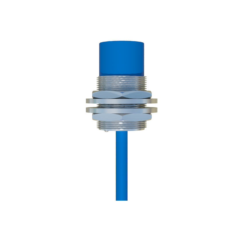
Capacitive proximity sensors share a similar oscillator-based principle but are sensitive to both conductive and non-conductive materials. The sensing element forms one plate of a capacitor, with the target object acting as the other plate (or altering the dielectric constant between plates). The circuit often incorporates a relaxation oscillator or an RC phase-shift oscillator where the sensing capacitance is part of the frequency-determining network. The presence of a target changes the effective capacitance, thereby shifting the oscillation frequency or amplitude. A frequency-to-voltage converter or amplitude demodulation circuit processes this shift. Due to their sensitivity to moisture, dust, and other environmental factors, capacitive sensor circuits require careful guarding and shielding techniques. A driven guard ring, held at the same potential as the sensor electrode, is commonly used to focus the electric field and eliminate the effects of parasitic capacitance to ground, ensuring stable operation and preventing false triggering.
Photoelectric sensors, particularly diffuse-reflective types used for proximity detection, rely on a modulated light source and a receiver circuit. The transmitter circuit typically uses a pulsed infrared LED driven by a constant current source. Pulsing the LED at a specific frequency (e.g., 5-50 kHz) allows the receiver circuit to distinguish the sensor's own light from ambient light. The receiver consists of a phototransistor or photodiode connected to a high-gain, low-noise amplifier. The amplified signal passes through a band-pass filter tuned to the modulation frequency, effectively rejecting DC light and low-frequency noise. The filtered signal is then rectified and compared to a threshold. This synchronous detection method provides excellent immunity to ambient light interference. Design priorities include selecting lenses for optimal beam shape, protecting the optical components from contamination, and implementing fail-safe monitoring for LED degradation.
Beyond the core sensing element, the complete circuit diagram of any industrial proximity sensor includes several critical supporting blocks. A robust power supply section is paramount, featuring reverse polarity protection, overvoltage clamping (using TVS diodes), and voltage regulation. For sensors with analog outputs (0-10V, 4-20mA), a precision output driver stage with short-circuit protection is necessary. Digital output circuits (PNP/NPN) require solid-state switches (like MOSFETs) with sufficient current rating and flyback diodes for inductive load protection. Modern sensors integrate microcontrollers for advanced functions: digital signal processing for filtering, temperature compensation algorithms, programmability of sensing modes, and communication interfaces (IO-Link). This intelligence allows for diagnostics, parameter setting, and enhanced performance.
When implementing these circuits, engineers must adhere to stringent EMC standards (like IEC 60947-5-2). This involves strategic PCB layout with clear separation of analog and digital grounds, use of ferrite beads, and proper filtering on all I/O lines. Housing design must provide both mechanical protection and EMI shielding. Ultimately, a successful proximity sensor circuit balances sensitivity, speed, immunity to environmental interference, and long-term reliability, forming the silent, intelligent backbone of automated systems from packaging machinery to robotic assembly cells.