In the realm of industrial automation and machine control, proximity sensors are indispensable components for non-contact object detection. Among the various configurations, the normally closed (NC) 3-wire proximity sensor stands out for its specific safety and circuit design applications. This article delves into the operational principles, wiring methodologies, and practical considerations for this critical sensor type, providing essential knowledge for electrical engineers and technicians.
A proximity sensor, fundamentally, detects the presence or absence of an object within its sensing range without physical contact. It achieves this through electromagnetic fields (inductive type for metals), capacitive fields, or ultrasonic waves. The "normally closed" designation refers to the state of its output signal circuit when the sensor is in its idle or non-activated state. In an NC configuration, the output switch is closed, allowing current to flow through the signal line when no target is present. When a target enters the sensing field, the switch opens, interrupting the signal circuit. This behavior is the inverse of the more common normally open (NO) configuration.
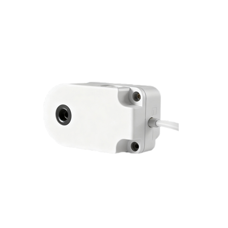
The 3-wire design is the standard for DC-powered sensors, providing a reliable and straightforward interface with programmable logic controllers (PLCs) and other control systems. The three wires are universally color-coded: Brown for the positive DC supply voltage (typically 10-30V DC), Blue for the common negative or 0V, and Black for the output signal. It is crucial to note that the Black wire's function is defined by the sensor's logic (NC or NO). For a normally closed sensor, the Black wire is internally connected to the positive supply (Brown) via the closed switch when idle. Upon detection, this connection is broken.
Wiring a normally closed 3-wire sensor requires careful attention. The Brown wire connects to the positive terminal of the DC power source. The Blue wire connects to the negative terminal of the same source and, critically, also to the common (COM) or negative input of the load (e.g., a PLC digital input). The Black (signal) wire connects directly to the load's input terminal. In this setup, when no target is detected, the closed switch completes the circuit from Brown, through the switch, out through Black, into the PLC input. This presents a "high" or "logic 1" signal (at the supply voltage) to the controller, indicating the "idle" state. Detection of a target opens the switch, dropping the voltage on the Black wire to near zero (pulled down by the load's internal circuitry), creating a "low" or "logic 0" signal.
The primary advantage of a normally closed configuration lies in fail-safe design. Consider a critical safety interlock or a wire break detection scenario. If the wire connecting the sensor's Black signal line to the PLC is severed, the circuit is broken, and the PLC input will read "low" or "0". This loss-of-signal condition can be programmed to trigger a machine stop or an alarm, indicating a fault. In a normally open configuration, a wire break would leave the PLC input floating or low, which might be indistinguishable from the sensor's active state (also low), creating a potentially dangerous undetected fault. Therefore, NC sensors are often specified for safety-related monitoring where a broken wire must cause a safe shutdown.
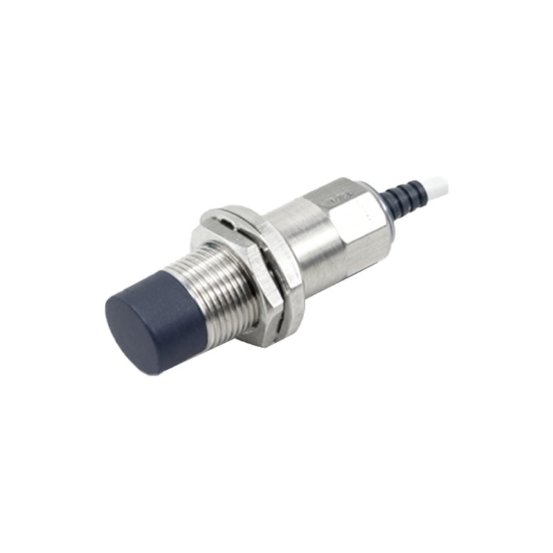
Selection criteria for a 3-wire NC proximity sensor extend beyond just the output logic. Engineers must consider the sensing type (inductive for metals, capacitive for non-metals), sensing distance, housing material (e.g., nickel-plated brass, stainless steel for harsh environments), electrical specifications (voltage range, current sinking/sourcing compatibility with the PLC), and environmental ratings (IP67, IP69K for washdown). Inductive sensors, the most common type, are further characterized by their sensing range, typically a fraction of their face diameter, and whether they are shielded (flush-mountable) or unshielded.
Troubleshooting common issues involves systematic checks. A multimeter is an essential tool. First, verify power between Brown (+) and Blue (-) wires. Next, measure the voltage on the Black wire relative to Blue. For an idle NC sensor with no target present, you should read the full supply voltage (e.g., 24V). When a target is presented, this voltage should drop to near 0V. If the voltage remains high when a target is present, the sensor may be faulty, the target may be outside its sensing range or made of an incompatible material, or the sensing face may be contaminated. Always consult the manufacturer's datasheet for specific voltage tolerances and timing diagrams.
In conclusion, the normally closed 3-wire proximity sensor is a vital component in designing robust and fail-safe control systems. Its inherent wiring fault detection capability makes it a preferred choice for applications where