Proximity sensors are indispensable components in modern industrial automation, providing non-contact detection of metallic and, in some cases, non-metallic objects. Their reliability, long operational life, and high-speed response make them ideal for applications ranging from object counting and position verification to machine safety and speed monitoring. However, the performance and longevity of these sensors are heavily dependent on correct installation. Improper mounting or environmental neglect can lead to erratic behavior, reduced sensing range, premature failure, and costly downtime. This article outlines the critical installation points that engineers and technicians must consider to ensure optimal sensor performance.
The first and foremost consideration is the selection of the correct mounting style and ensuring proper physical installation. Proximity sensors are available in various housing styles, including cylindrical (threaded barrel), rectangular, and ring-shaped. For cylindrical sensors, the mounting hole must be drilled to the exact specified diameter and depth. An oversized hole can cause the sensor to move, affecting alignment and repeatability. The sensor should be mounted securely using the appropriate locknut, ensuring it is flush or recessed as per the manufacturer's guidelines. A critical rule is to maintain the recommended lateral and axial clearance between the sensor face and any surrounding metal. Insufficient clearance can cause the sensing field to be influenced by the mounting bracket or machine frame, a phenomenon known as "shielding" or "side-metal effect," which drastically reduces the effective sensing distance. Typically, a clearance of one to two times the sensor's housing diameter is required.
Environmental factors constitute the second major area of concern. Industrial environments are often harsh, featuring contaminants like dust, coolant, metal chips, and strong electromagnetic interference (EMI). For wet or dusty conditions, selecting a sensor with an appropriate Ingress Protection (IP) rating, such as IP67 or IP69K, is essential. The sensor must be installed in a location where accumulated debris cannot build up on the active sensing face, as this will attenuate the sensing field. In applications involving welding equipment or large motors, EMI can induce false signals in the sensor or its cabling. To mitigate this, use shielded cables, ensure proper grounding of the sensor body and shield (drain wire), and route sensor cables away from high-power lines. In extreme cases, sensors with welded metal housings and advanced EMI immunity ratings should be specified.
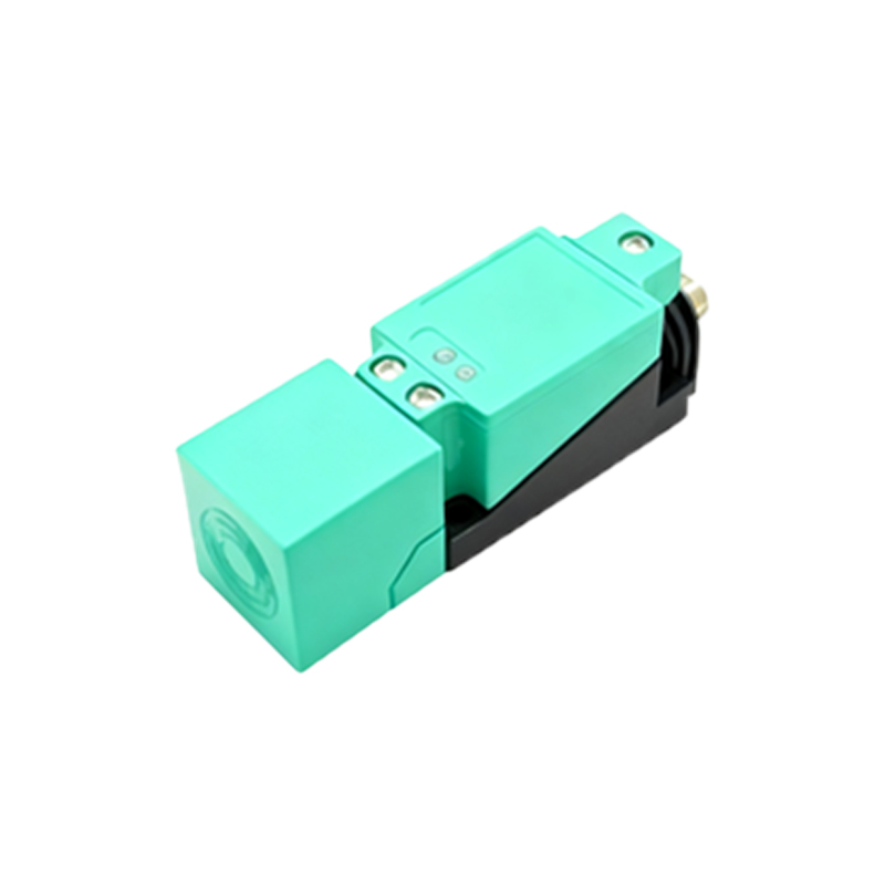
Electrical wiring and connection integrity are equally vital. Always adhere to the sensor's datasheet for voltage requirements (e.g., 10-30V DC, 90-250V AC) and wiring diagrams (PNP vs. NPN, normally open vs. normally closed). Incorrect voltage can destroy the sensor instantly. For DC sensors, strict polarity must be observed. The load (e.g., a PLC input, relay, or indicator lamp) must be connected in series with the sensor's output. A common mistake is to short-circuit the output. Wires should be of adequate gauge, and connections must be tight and corrosion-free. For long cable runs, consider voltage drop, especially with 2-wire AC/DC sensors. It is highly recommended to use conduit or cable carriers to protect the wiring from physical damage. Furthermore, never test a sensor by shorting its leads to a power source; always use the intended target object.
Finally, thorough testing and commissioning under actual operating conditions are non-negotiable. After installation, verify the sensing distance with the actual target material, size, and approach direction. The rated sensing distance (Sn) is defined for a standard mild steel target. Different materials (e.g., stainless steel, aluminum, copper) have correction factors that reduce the effective range. Ensure the target approaches the sensor perpendicularly to the sensing face for maximum reliability. Check for the presence of any "blind zones" very close to the sensor face where detection may not occur. Observe several operating cycles to confirm consistent switching without chatter. Adjust the sensor's position if necessary to account for mechanical tolerances or thermal expansion in the machinery. Implementing these installation best practices will maximize system uptime, enhance safety, and ensure that your proximity sensors deliver the precise, reliable performance that modern automation systems demand.