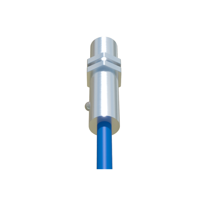
In the realm of industrial automation and electrical engineering, proximity switch sensors are indispensable components that enable non-contact detection of objects. These sensors operate based on electromagnetic, capacitive, or inductive principles, providing reliable performance in harsh environments where mechanical switches might fail. This article delves into the visual aspects of electrical proximity switch sensors, using images to elucidate their design, functionality, and applications.
A typical proximity switch sensor image reveals a compact, cylindrical or rectangular housing, often made of durable materials like stainless steel or nickel-plated brass to withstand moisture, dust, and temperature fluctuations. The sensor body usually features threaded sections for easy mounting in control panels, machinery, or conveyor systems. Key visual elements include the sensing face, which is the active area where detection occurs, and indicator LEDs that signal power status or object detection. For instance, in inductive proximity sensors, the sensing face contains a coil that generates an electromagnetic field; when a metallic object enters this field, it triggers a switch signal. Images often highlight this with cross-sectional diagrams showing internal components like oscillators, amplifiers, and output circuits.
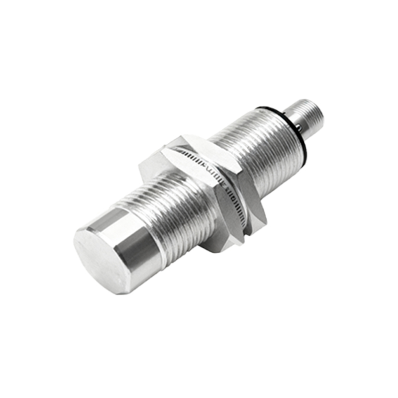
High-quality photos or technical drawings of proximity switch sensors also emphasize wiring connections. Most sensors have three or four wires: brown for positive voltage, blue for negative or ground, black for output signal, and sometimes white for additional functions like complementary output. Visual guides frequently include wiring schematics to illustrate how these sensors integrate into control systems, such as PLCs (Programmable Logic Controllers) or relay modules. For example, a PNP (sourcing) sensor image might show the black wire connected to a load, while an NPN (sinking) sensor image depicts a different configuration, aiding engineers in proper installation.
Applications of proximity switch sensors are vast, and images can effectively demonstrate their use in real-world scenarios. In automotive manufacturing, sensors detect the position of robotic arms or parts on assembly lines, with photos showing sensors mounted near moving components. In packaging industries, they count products on conveyors, where images capture sensors aligned with item flow. Additionally, safety systems employ these sensors for door monitoring or machine guarding, with visuals highlighting their placement in hazardous areas. Technical images often include distance specifications, such as sensing ranges from 2mm to 60mm, depending on the sensor type and target material.
When analyzing sensor images, it's crucial to note certifications like IP67 or IP68 ratings, which indicate protection against dust and water ingress. These ratings are typically visible on sensor labels in photos, ensuring compliance with industry standards. Moreover, images of specialized sensors—such as high-temperature variants for foundries or washdown models for food processing—show unique features like extended cables or reinforced seals. Diagrams may also compare different output types: digital (on/off) signals for simple detection versus analog outputs for distance measurement, with graphs illustrating response curves.
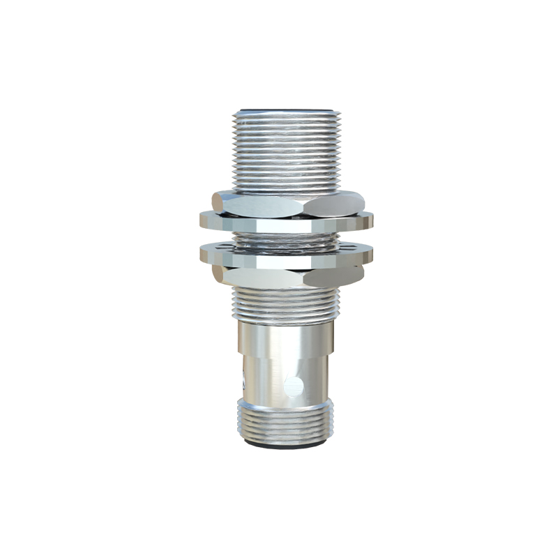
In conclusion, visual resources play a vital role in understanding electrical proximity switch sensors. By examining images and diagrams, engineers can grasp design nuances, installation procedures, and operational principles. This enhances troubleshooting, selection, and implementation in diverse industrial settings, ultimately boosting efficiency and safety. For those seeking to deepen their knowledge, referring to manufacturer catalogs or online galleries with annotated images is recommended, as they provide up-to-date insights into sensor technology advancements.