Proximity switch sensors, as non-contact detection devices, have become indispensable components in modern industrial automation systems. Their core functionality relies on sophisticated microcircuitry that enables precise, reliable, and rapid object detection without physical contact. This article delves into the design principles, operational characteristics, and application considerations of the microcircuits within inductive, capacitive, and photoelectric proximity sensors.
The heart of an inductive proximity sensor is an oscillator circuit built around a coil (the sensor's active face). This oscillator generates a high-frequency electromagnetic field. When a metallic object enters this field, eddy currents are induced on the object's surface. These eddy currents draw energy from the oscillator, causing a reduction in its oscillation amplitude. A subsequent monitoring circuit, typically comprising a Schmitt trigger or a specialized IC, detects this amplitude change. Once the amplitude drop exceeds a predefined threshold, the circuit triggers a solid-state output switch (usually an NPN or PNP transistor) to change state, signaling the presence of the target. Key microcircuit design challenges here involve stabilizing the oscillator against temperature drift and electrical noise, ensuring consistent sensing distance, and providing short-circuit and reverse-polarity protection.
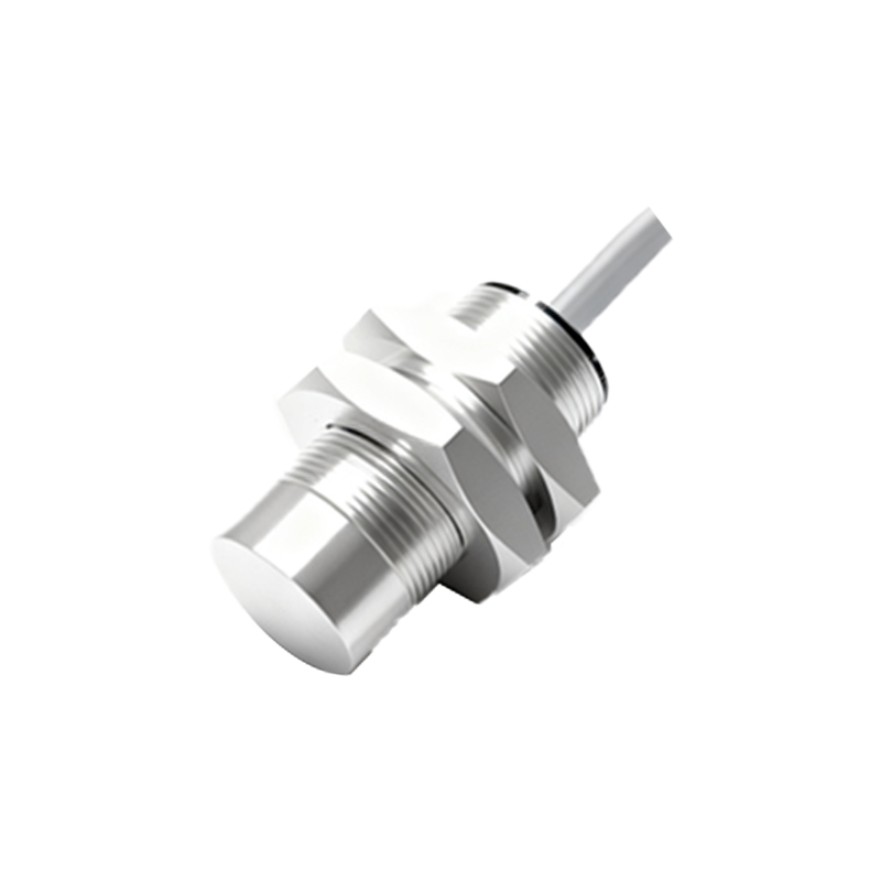
Capacitive proximity sensors operate on a similar principle but are sensitive to both conductive and non-conductive materials. Their microcircuit utilizes a capacitive plate connected to an oscillator. The presence of any material with a dielectric constant different from air alters the capacitance of the system, which in turn changes the oscillator's frequency or amplitude. A evaluation circuit measures this change. The microcircuit design often includes sensitivity adjustment potentiometers or digital trimming capabilities, allowing the sensor to be tuned for specific materials, such as liquids through a container wall or granular solids in a hopper. Advanced ICs integrate the oscillator, demodulator, and output driver in a single package, significantly reducing the PCB footprint and enhancing reliability.
Photoelectric sensors, while often grouped separately, share the microcircuit complexity of proximity devices. The microcircuit in a through-beam or retro-reflective sensor continuously monitors the photodiode or phototransistor receiver's current. A high-gain amplifier circuit boosts the minute signal. A comparator circuit then contrasts this amplified signal with a reference voltage. An object interrupting the light beam causes the signal to fall below the threshold, triggering the output. For diffuse reflective types, the circuit must be exceptionally sensitive to distinguish the weak reflected signal from ambient light noise, often incorporating modulated LED light sources and synchronous detection circuits to achieve high noise immunity.
Modern proximity sensor microcircuits leverage Application-Specific Integrated Circuits (ASICs) and microcontrollers. An ASIC consolidates analog front-end signal conditioning, digital logic for processing, and output driving into one chip. This integration offers superior performance consistency, lower power consumption, and enhanced features like programmable sensing ranges, output delay timers (ON/OFF delay), and diagnostic LED driving logic. Communication capabilities are also being integrated; IO-Link interfaces, for instance, are now embedded into the sensor's microcircuit, enabling parameter setting, process data monitoring, and advanced diagnostics directly from the controller.
From a design engineering perspective, several critical factors must be addressed in the microcircuit layout. Proper grounding and shielding are paramount to prevent electromagnetic interference (EMI) from affecting the sensitive oscillator or amplifier stages. Power supply decoupling using capacitors placed close to the IC power pins is essential for stable operation. The output stage design must consider load types (relays, PLC inputs, etc.), inrush currents, and protection against inductive kickback from solenoids or motors. Furthermore, designing for harsh industrial environments necessitates incorporating surge protection, electrostatic discharge (ESD) protection diodes, and conformal coating on the PCB to withstand humidity, dust, and chemical exposure.
In application, selecting the right sensor involves matching the microcircuit's characteristics to the task. For high-speed counting on a packaging line, a sensor with a fast-response microcircuit and a switching frequency exceeding 1 kHz is required. In welding environments, sensors with microcircuits immune to strong magnetic fields are crucial. For food and beverage applications, stainless-steel housed sensors with wash-down resistant circuitry are standard. Understanding the underlying microcircuit technology empowers engineers to optimize sensor placement, troubleshoot false triggering issues related to electrical noise or mutual interference, and implement robust automated systems.
The evolution of proximity sensor microcircuits continues toward miniaturization, intelligence, and resilience. The integration of more advanced diagnostics, such as condition monitoring (predicting coil degradation or lens contamination), and the fusion of multiple sensing principles (e.g., inductive and capacitive in one housing) on a single, powerful microcircuit platform, will further solidify their role as the fundamental enablers of efficient and smart industrial automation.