In the world of industrial automation, machine safety, and smart devices, proximity sensors are the silent sentinels. These non-contact devices detect the presence or absence of an object, triggering a crucial action in a system. While much attention is given to the sensor head itself—its sensing technology, range, and housing—the humble connection wire is the vital lifeline that carries power to the sensor and signals back to the controller. Understanding proximity sensor connection wires is fundamental to ensuring reliable operation, system integrity, and long-term performance.
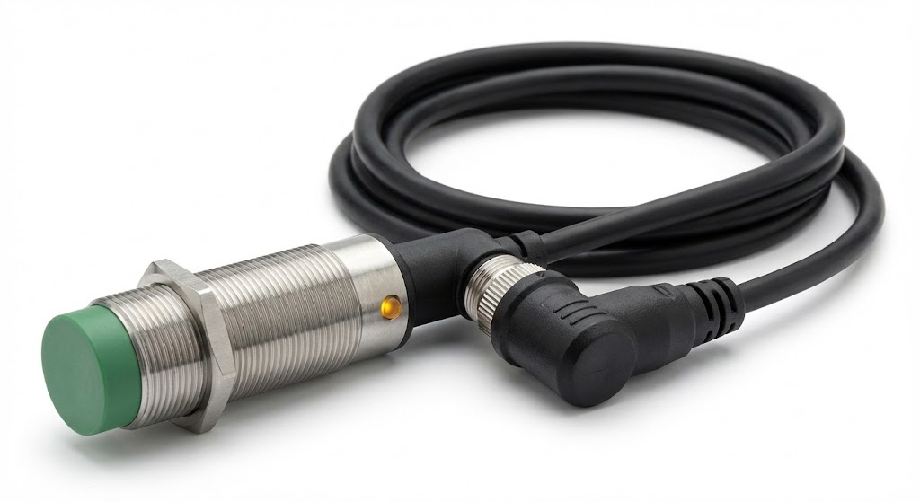
At its core, a proximity sensor connection wire assembly, often called a sensor cable or cordset, serves three primary functions: power supply, signal transmission, and physical connection. The wire connects the sensor to a programmable logic controller (PLC), a relay, or another interface device. The quality, type, and installation of these wires directly impact the sensor's immunity to electrical noise, its durability in harsh environments, and the overall stability of the control loop.
Types of Connection Wires and Connectors
Proximity sensors typically use one of two connection methods: pre-wired cables or quick-disconnect connectors. Pre-wired cables are permanently attached to the sensor, with the other end stripped for direct connection to a terminal block. They are simple and cost-effective but offer less flexibility for maintenance. Quick-disconnect systems, on the other hand, use standardized connectors (like M8, M12, or M23 circular connectors). The sensor has a male connector, and a separate cable with a female counterpart plugs into it. This allows for easy sensor replacement without rewiring. The M12 connector, with its 4-pin or 2-pin configuration, has become an industry standard for DC sensors, while 3-pin versions are common for AC models. The choice between these types depends on the application's need for maintenance, environmental sealing (IP rating), and initial setup complexity.

Wire Composition and Shielding
The internal construction of the wire is critical. A standard connection wire for industrial sensors consists of multiple conductors—usually two, three, or four wires—each insulated and color-coded according to international standards (e.g., brown for +V, blue for 0V/common, black for output signal, and white for a second output or diagnostic). These conductors are surrounded by an inner sheath, a shielding layer, and an outer jacket.
Shielding is arguably the most important feature for reliable signal transmission. Electrical noise from motors, frequency drives, and power lines can induce stray voltages in the sensor wires, causing false triggering or signal loss. A braided copper or aluminum foil shield acts as a Faraday cage, diverting this electromagnetic interference (EMI) to ground. For optimal performance, the shield must be properly grounded at the controller end, typically using a connector with a 360-degree shield clamp or a dedicated drain wire.
Installation Best Practices
Proper installation prevents a multitude of problems. Wires should be routed separately from high-power cables. Running sensor cables in the same conduit or cable tray as AC power lines is a common mistake that guarantees interference. Maintain a minimum separation distance, ideally 20-30 cm. Use cable glands or strain relief fittings at the sensor entry point to protect the connection from pull-out and ensure the environmental seal remains intact. Avoid sharp bends; adhere to the cable's minimum bend radius specification to prevent damage to the internal conductors and shield. When using quick-disconnect plugs, ensure they are fully seated and locked, and that the mating seal is clean to maintain the IP rating.
Common Issues and Troubleshooting
Many sensor failures can be traced back to connection wiring. Intermittent operation often points to a broken wire inside the insulation, a loose connection at the terminal block, or a corroded connector pin. Complete failure can result from a short circuit due to damaged insulation or incorrect wiring (e.g., connecting 24V to the output wire). Persistent false signals usually indicate inadequate shielding or improper grounding of the shield. A systematic approach to troubleshooting involves checking for continuity in each conductor, verifying voltage at the sensor terminals with a multimeter, and inspecting the physical condition of the cable and connector for cuts, kinks, or chemical degradation.
Selecting the Right Wire for the Environment
Not all wires are created equal. The application environment dictates the necessary specifications. For washdown areas in food and beverage plants, cables need a smooth, chemical-resistant PVC or PUR outer jacket that can withstand frequent cleaning with harsh agents. In high-temperature zones near ovens or welding stations, wires with silicone or Teflon jackets are essential. For continuous flexing applications, such as on robot arms or moving machine parts, specially designed highly flexible cables with fine-stranded conductors are required to withstand millions of bend cycles without failure. Always match or exceed the IP rating of the sensor