In industrial automation and control systems, proximity sensors are indispensable components for detecting the presence or absence of objects without physical contact. Among the various types available, two-wire and three-wire DC sensors are prevalent. However, scenarios often arise where a two-wire sensor must be integrated into a three-wire system due to equipment compatibility, legacy system upgrades, or specific design constraints. This article provides a comprehensive technical guide for engineers on properly connecting a two-wire DC proximity sensor to a three-wire system, ensuring reliable operation and system integrity.
Understanding the fundamental differences between the two configurations is crucial. A typical two-wire DC proximity sensor operates similarly to a switch in series with the load. It has two terminals: one connects to the positive DC supply voltage, and the other connects to the load, which then returns to the negative side (common ground) of the supply. The sensor itself consumes a small amount of quiescent current (leakage current) even in its "off" state to power its internal electronics. When it detects a target, it switches on, allowing the full load current to flow. Key specifications here are the residual current (when off) and voltage drop (when on).
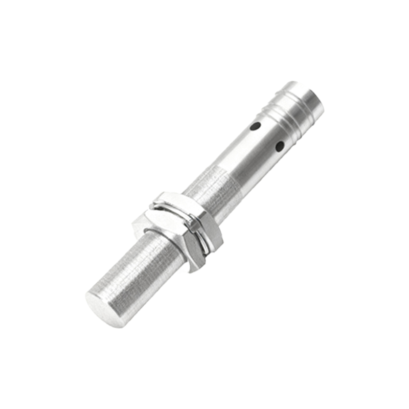
A standard three-wire DC sensor, in contrast, has separate wires for power supply and the output signal. It typically features a brown wire (for DC+), a blue wire (for DC- or common), and a black wire (for the switched output). This design provides a clear separation between the sensor's internal power circuit and its output switching element (often an NPN or PNP transistor). The output transistor switches the load connected to the black wire, either sourcing current (PNP) or sinking current (NPN) relative to the common (blue) wire.
The core challenge in connecting a two-wire sensor to a three-wire system lies in the system's expectation of a discrete, low-leakage signal from the third wire (output), while the two-wire sensor presents a two-terminal device with inherent leakage. The primary goal is to make the two-wire sensor's behavior compatible with the three-wire input module (e.g., a PLC digital input).
The most common and recommended method involves using the two-wire sensor to drive an intermediate relay, whose contacts then interface with the three-wire system. Connect the positive supply voltage to one terminal of the two-wire sensor. Connect the sensor's other terminal to one coil terminal of a DC relay. Connect the other relay coil terminal to the negative supply common. Ensure the relay's coil voltage matches the supply voltage and its current rating is above the sensor's minimum operating current but below its maximum switching current. The relay's normally open (NO) or normally closed (NC) contact (depending on the logic required) is then wired to the three-wire input. For example, connect one contact to the PLC's input point and the other contact to the PLC's common or positive reference, configuring it as a dry contact input. This method provides complete electrical isolation, handles leakage current without issue, and protects sensitive PLC inputs.
Alternatively, for direct connection in low-leakage scenarios, a bypass resistor (also called a bleeding resistor) can be used. Many three-wire input modules have a minimum current threshold to recognize an "ON" state. The residual current of a two-wire sensor might be too low to reliably switch the input to "OFF." By wiring a resistor in parallel with the PLC input, a bypass path is created for the sensor's leakage current, preventing false ON signals. The resistor value is calculated based on the supply voltage and the sensor's maximum residual current. For instance, with a 24V DC supply and a sensor leakage of 1.8 mA, a resistor of approximately 13.3 kΩ (24V / 0.0018A) with sufficient wattage (e.g., 0.5W) can be used. Connect one sensor wire to DC+, the other sensor wire to the PLC input, and then connect the bypass resistor between the PLC input and DC-. This method is less robust than the relay method and requires careful calculation to avoid affecting the ON-state signal.
Critical considerations must be observed. First, always verify voltage compatibility. Second, meticulously check the current ratings: the two-wire sensor's load current must be within its specified range, and the total current drawn (sensor plus connected load/relay coil) must not exceed its maximum. The sensor's leakage current must be lower than the three-wire input module's OFF-state current threshold to prevent false triggering; otherwise, the bypass resistor or relay method is mandatory. Polarity is vital for DC sensors; incorrect connection can cause permanent damage. Finally, account for voltage drop across the two-wire sensor in the ON state, which may reduce