In industrial automation and precision control systems, the lateral accuracy of a proximity sensor is a critical performance parameter. It refers to the sensor's ability to consistently and correctly detect a target's presence or absence when the target approaches from a direction perpendicular to the sensor's sensing face. Poor lateral accuracy can lead to missed detections, false triggers, and ultimately, process failures. This guide provides a systematic, engineering-focused approach to adjusting and optimizing the lateral accuracy of inductive, capacitive, and photoelectric proximity sensors.
Understanding the Fundamentals of Lateral Sensing
Before adjustment, it is essential to understand the sensor's sensing field characteristics. Unlike the rated sensing distance (Sn), which is measured axially, lateral accuracy concerns the "width" or "profile" of the detection field. This field is not a perfect geometric shape; its boundaries are defined by specific detection thresholds. For inductive sensors, the field is influenced by the oscillator coil design and the target material. For capacitive sensors, it's affected by the electrode plate configuration and dielectric constant of the target. Photoelectric sensors (diffuse, retro-reflective, through-beam) have lateral accuracy dictated by the light beam's divergence and the receiver's field of view. Always consult the manufacturer's datasheet for the lateral sensing characteristic diagrams.
Step-by-Step Adjustment Procedure
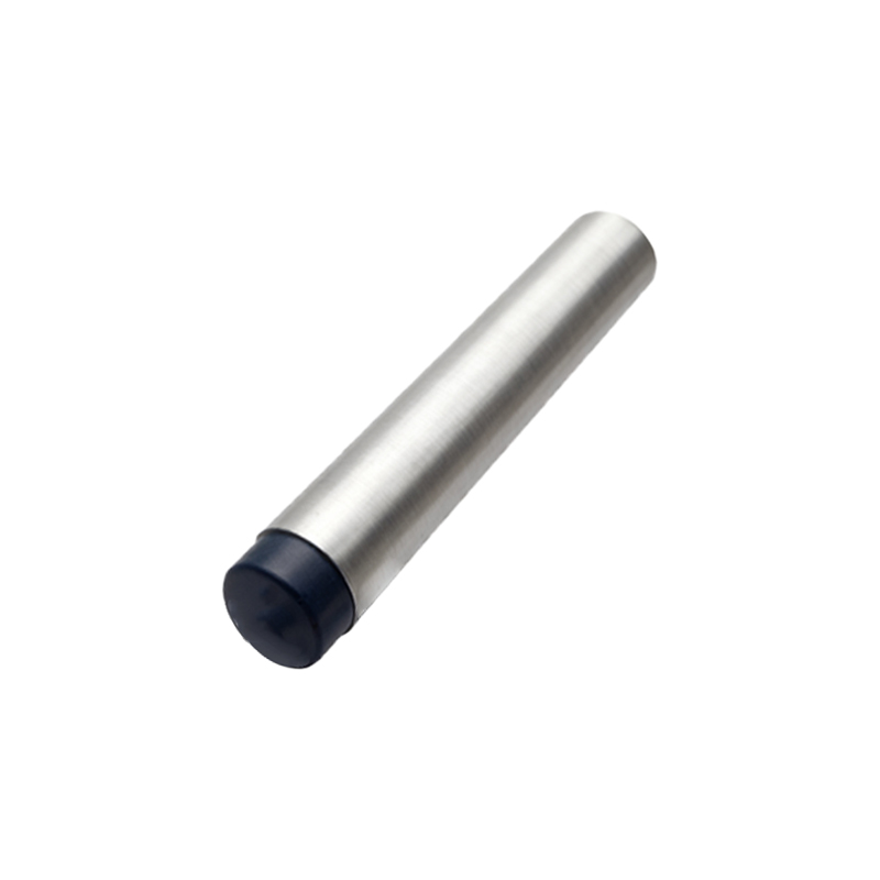
1. Selection and Mounting: Begin with the correct sensor for the application. Consider the target material, size, required sensing distance, and environmental factors (e.g., washdown, temperature, EMI). Ensure rigid, vibration-free mounting. Any play or movement in the sensor bracket will directly degrade lateral accuracy. Use precision-machined brackets and high-grade fasteners.
2. Initial Alignment and Calibration: Manually position the target at the desired lateral detection point. Using a precision positioning stage (e.g., a micrometer slide) is highly recommended. Power the sensor and observe its output state (LED indicator or PLC input). Slowly move the target laterally into the suspected sensing zone. Mark the precise point where the output switches (the "actuation point"). Repeat this from the opposite direction to find the "release point." The difference between these points relates to hysteresis, but the repeatability of the actuation point is key for lateral accuracy.
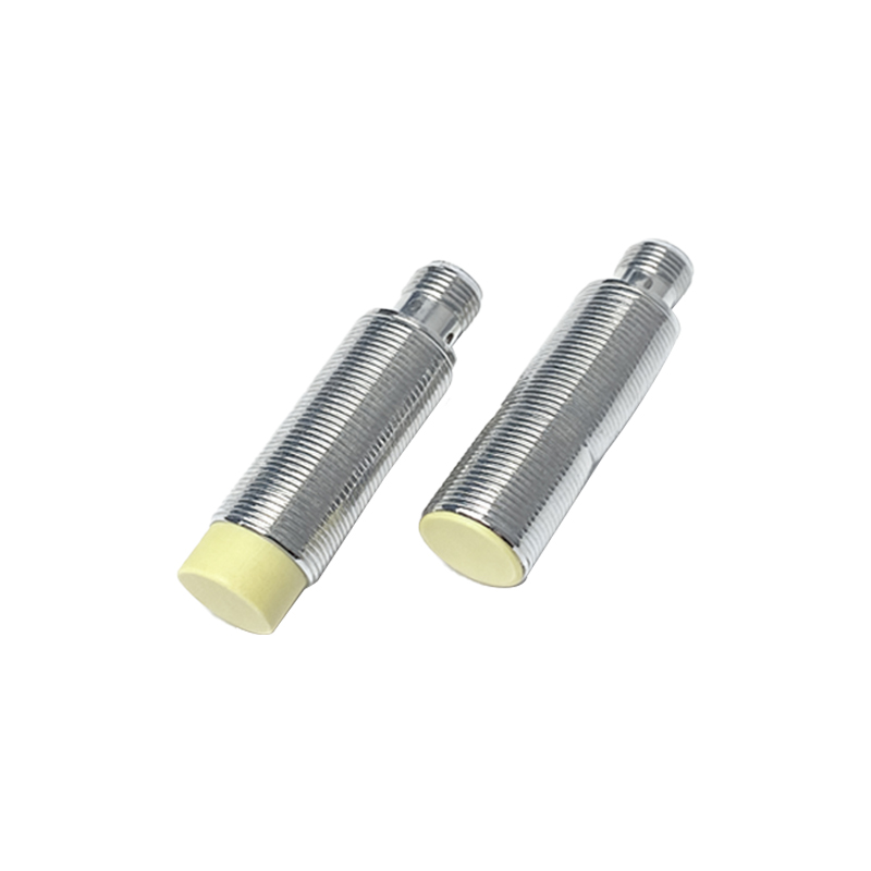
3. Fine-Tuning with Sensitivity Adjustment: Many modern proximity sensors feature a potentiometer or digital means for sensitivity adjustment. This control effectively expands or contracts the overall sensing field, including its lateral profile.
To Improve Accuracy for a Small Target: If the target is smaller than the sensor's face, you may need to reduce sensitivity. This shrinks the sensing field, creating a more defined lateral boundary and preventing detection of adjacent objects or the background. This is crucial in dense packaging or assembly lines.
To Ensure Detection of a Large or Misaligned Target: If the target has potential for lateral variance in its path, a slight increase in sensitivity can widen the lateral field, providing a safety margin. However, this must be balanced against the risk of false triggering.
4. Utilizing Shielding and Baffles: Mechanical solutions are often the most effective. For photoelectric sensors, installing tubular shrouds or slit apertures physically restricts the light beam's lateral spread, creating a very precise detection zone. For inductive sensors, using ferrous metal shields (e.g., steel plates) around the sides of the sensor can shape the electromagnetic field, blocking interference from adjacent metallic objects and sharpening lateral definition.
5. Electrical and Environmental Compensation: Electrical noise can cause signal instability, manifesting as inconsistent lateral detection. Ensure proper grounding, use shielded cables, and keep sensor wiring separate from power lines. For capacitive sensors, the adjustment must account for changes in ambient humidity or the presence of contaminant films, which may require periodic re-calibration of the sensitivity.
6. Validation and Testing: After adjustment, perform a rigorous repeatability test. Cycle the target through its intended lateral path hundreds or thousands of times while monitoring the sensor output. Statistical process control (SPC) methods can be applied to calculate the repeatability standard deviation. This data quantifies the achieved lateral accuracy. Environmental stress tests (temperature cycles, vibration) should also be conducted if applicable.
Advanced Techniques and Sensor Selection
For ultra-high-precision applications, consider specialized sensors:
Factor-1 Inductive Sensors: Designed to detect all metals at the same range, providing more consistent lateral performance with different target materials.
Background Suppression Photoelectric Sensors: These use triangulation or time-of-flight principles to detect only objects within a precise window, offering exceptional lateral and depth discrimination.
Analog Output Sensors: Instead of a simple on/off switch, these provide a continuous current or voltage proportional to distance. By monitoring the analog