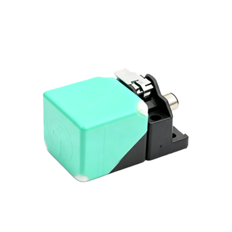
Proximity sensors are indispensable components in modern industrial automation, providing non-contact detection of metallic or non-metallic objects. Correct installation is critical to ensure reliable operation, longevity, and safety in demanding environments such as manufacturing lines, robotics, and machinery. This guide outlines professional procedures for installing inductive, capacitive, and magnetic proximity sensors, adhering to industry standards.
Before installation, verify the sensor specifications, including sensing distance, output type (PNP/NPN, NO/NC), voltage rating, and housing material. Ensure the power supply is disconnected to prevent electrical hazards. Select an appropriate location free from excessive vibration, heat, or contaminants. For inductive sensors (used for metal detection), maintain a clearance of at least twice the rated sensing distance from surrounding metal objects to avoid false triggering. Capacitive sensors (for non-metallic materials) require similar isolation from interfering substances.
Mounting the sensor securely is the first physical step. Use the provided brackets or threaded barrels to fix the sensor in position. For cylindrical sensors, standard metric or NPT threads allow direct mounting into drilled holes. Ensure the sensor is aligned parallel to the target object’s approach direction. The sensing face must be perpendicular to the target’s surface for optimal performance. Avoid overtightening, which can damage the housing or affect sensitivity. In high-vibration settings, consider using shock-absorbing mounts.
Wiring must comply with local electrical codes and the sensor’s datasheet. Typically, proximity sensors have three or four wires: brown (power+), blue (power-), black (output), and sometimes white (complementary output). For DC sensors, connect the brown wire to the positive terminal and blue to negative. PNP sensors switch positive voltage to the load; NPN sensors switch negative. Use shielded cables in environments with electromagnetic interference (EMI), grounding the shield at the controller end only. Keep signal cables separate from high-power lines to prevent noise induction. After wiring, secure cables with cable glands or ties to prevent strain on connections.
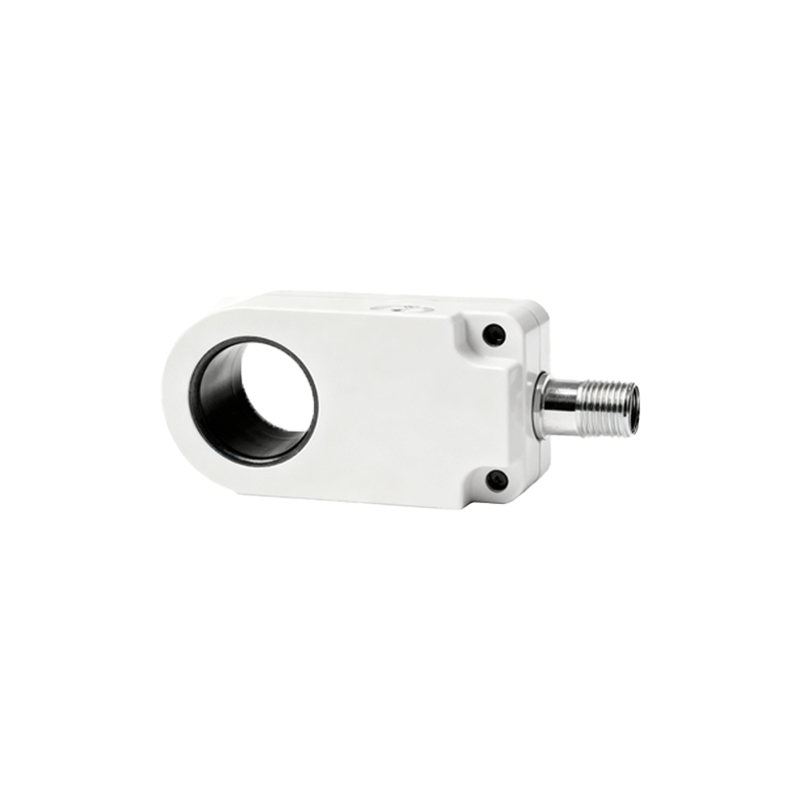
Adjustment and testing follow installation. Power the system and introduce a target object within the specified sensing range. Use the sensor’s potentiometer (if available) to fine-tune sensitivity, ensuring it detects the target reliably without reacting to background interference. For adjustable-range sensors, set the sensing distance to 70-80% of the maximum to account for environmental variations. Test with multiple cycles to verify repeatability. In applications involving fast-moving targets, consider response time specifications to avoid missed detections.
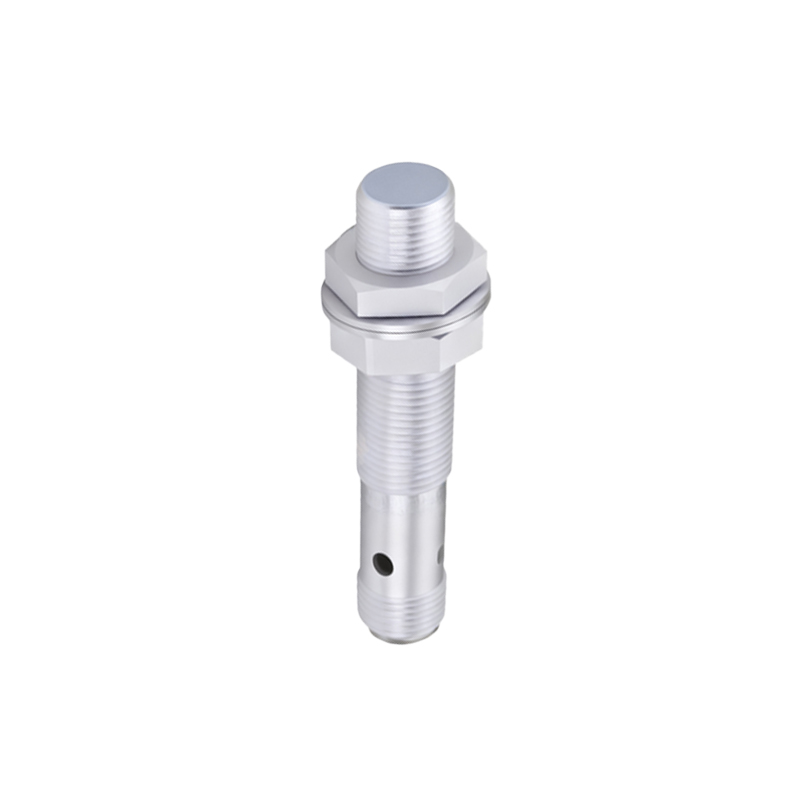
Maintenance involves periodic checks for physical damage, contamination, or loose connections. Clean the sensing face with a soft cloth to remove oil, dust, or debris that could reduce effectiveness. Document installation details, including date, location, and settings, for future reference. Common installation errors include incorrect wiring, inadequate clearance, and misalignment—all of which lead to operational failures.
By following these steps, engineers can ensure proximity sensors deliver precise, durable performance, enhancing system efficiency and reducing downtime. Always refer to manufacturer guidelines for model-specific instructions, as variations exist across products and applications.