Proximity sensors are indispensable components in modern industrial automation, playing a critical role in object detection, position sensing, and process control without physical contact. Their correct installation and wiring are paramount for ensuring system reliability, safety, and optimal performance. This guide details the fundamental wiring methods for various types of proximity sensors, adhering to industry standards and best practices.
Understanding Sensor Types and Outputs
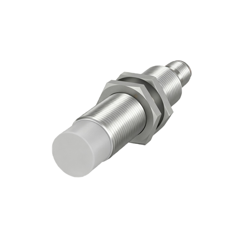
Before wiring, identifying the sensor type and its output configuration is essential. The two primary categories are:
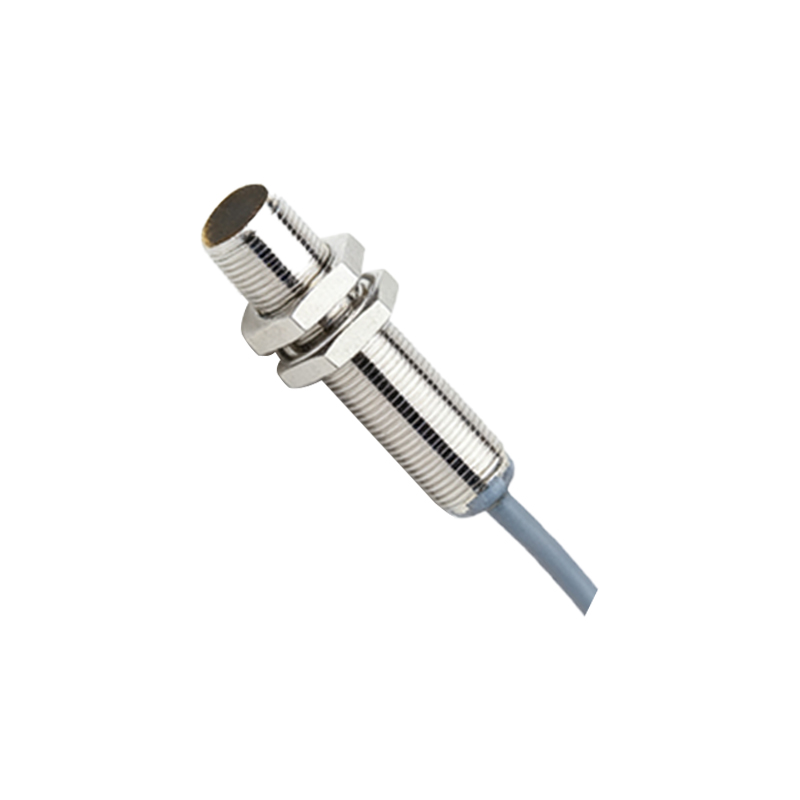
1. Inductive Proximity Sensors: Detect metallic objects. Common in machine tools and material handling.
2. Capacitive Proximity Sensors: Detect both metallic and non-metallic materials (e.g., plastics, liquids). Used in level detection and packaging.
Regarding outputs, sensors are classified as:
2-Wire AC/DC Sensors: Function similarly to a switch in series with the power supply and load. Wiring is simple, but they have a residual voltage drop when "on" and a leakage current when "off," which can affect certain control circuits.
3-Wire DC Sensors: The industry standard, offering separate wires for power supply positive (brown/red), power supply negative (blue/black), and the switched output signal (black/white). They provide NPN (sinking) or PNP (sourcing) outputs.
4-Wire DC Sensors: Essentially a 3-wire sensor with two complementary outputs (e.g., one NPN and one PNP, or one NO and one NC).
NAMUR Sensors: Intrinsically safe sensors used in hazardous areas, requiring a separate switching amplifier.
Standard Wiring Procedures for 3-Wire DC Sensors
This is the most common configuration. Always consult the manufacturer's datasheet for the specific pinout and wire color code (IEC standard: Brown = +V, Blue = 0V, Black = Output).
1. Power Supply Connection: Connect the Brown wire to the positive terminal of the DC power supply (typically 10-30V DC). Connect the Blue wire to the negative terminal (0V). Ensure the voltage matches the sensor's rating.
2. Output Load Connection: The Black (or sometimes White) wire is the switched output. Its connection depends on whether it is an NPN or PNP sensor.
PNP (Sourcing) Output: The sensor sources current to the load. Connect the Black output wire to one terminal of your load (e.g., PLC input, relay coil). Connect the other terminal of the load to the power supply's 0V (Blue wire).
NPN (Sinking) Output: The sensor sinks current from the load. Connect the Black output wire to the 0V (Blue wire). Connect one terminal of your load to the positive supply, and the other terminal of the load to the sensor's output wire.
3. Shielded Cable (Recommended): For environments with significant electromagnetic interference (EMI), use shielded cable. Connect the cable shield to a functional earth ground at the control panel end only. Do not connect the shield at both ends to avoid ground loops.
Wiring 2-Wire Sensors
Wiring a 2-wire sensor is analogous to wiring a conventional switch. Connect one wire to the power supply (L+ for DC or Phase for AC). Connect the other wire to your load. Finally, connect the other side of the load back to the power supply's return (L- or Neutral). Ensure the load's current draw is within the sensor's minimum and maximum switching current ratings to guarantee proper operation.
Critical Considerations for Reliable Operation
Power Supply Quality: Use a regulated, stabilized DC power supply. Ripple and noise can cause erratic sensor behavior.
Short-Circuit and Overload Protection: Always fuse the power supply line to the sensor. Some sensors have built-in protection, but external fusing is a key safety practice.
Avoiding Inductive Load Spikes: When switching inductive loads like relay coils, use a suppression device (flyback diode for DC, RC snubber or varistor for AC) across the load to protect the sensor's solid-state output from voltage transients.
Correct Sensing Distance: Maintain the specified sensing distance. Factors like target material, size, and approach angle can affect performance. For inductive sensors, mild steel is the standard reference; other metals reduce the effective sensing range.
Environmental Factors: Protect cables from abrasion, excessive bending, and exposure to oils, coolants, or UV radiation. Use conduit or cable carriers in harsh environments.
Wiring Separation: Keep sensor signal cables