In industrial automation and control systems, proximity switches are indispensable components for non-contact object detection. Among their various operational modes, the latching (or self-holding) function is critical for applications requiring state memory. This article provides a comprehensive technical guide to the wiring diagrams and principles of proximity switches configured as latching sensors.
Understanding Latching Function in Proximity Switches
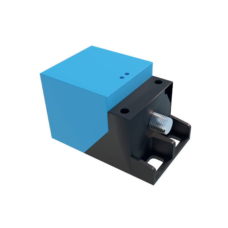
A standard proximity switch outputs a signal only when a target is within its sensing range. Once the target moves away, the output ceases. A latching proximity switch, however, "remembers" its last detected state. When a target enters the sensing field, the switch activates and locks into the ON state, maintaining the output signal even after the target departs. It will only reset to the OFF state when a specific reset condition is met, typically the detection of a second target or a dedicated reset signal. This function is essential in counting, batch processing, and safety interlock circuits where a transient detection must trigger a sustained action.
Core Wiring Configurations
The implementation of the latching function depends heavily on the sensor's internal design and output type. The two primary categories are 2-wire and 3-wire (or 4-wire) configurations with complementary output logic.
1. 2-Wire AC/DC Latching Sensors: These are simpler in connection but require careful consideration of the load. They integrate the latching logic internally. Wiring involves connecting one wire to the power supply (L+ or L1) and the other wire to the load, which then connects to the neutral (N) or DC negative. The latching and resetting are triggered by the physical presence of targets, often requiring a specific sequence or duration. The internal electronic circuit handles the state memory. The key in the diagram is to ensure the load current rating is within the sensor's switching capability.
2. 3-Wire DC Latching Sensors (PNP or NPN): This is the most common configuration for precise control. These sensors have separate wires for power supply (Brown/+V), ground (Blue/0V), and output (Black). The latching function is achieved through a second output wire or a dedicated control signal wire.
Dual-Output Type (Set/Reset): One output acts as the "Set" output (e.g., Black wire). It turns ON and latches when the first target is detected. A separate "Reset" output (e.g., White wire) activates when a second target (or reset actuator) is detected, breaking the latch and turning off the Set output. In wiring, both outputs share the same power and ground. The load (e.g., a PLC input, relay coil) is connected between the Set output and ground (for PNP) or between the Set output and +V (for NPN).
Control Signal Type: Some advanced models have a standard output plus a separate control pin for a latching enable/reset signal. This allows external devices like a PLC to command the latch or reset via a separate digital signal, offering greater system integration flexibility.
Detailed Wiring Diagram Analysis
Let's examine a typical wiring diagram for a 3-wire DC PNP sensor with dual complementary outputs (NO Set + NC Reset).
Power Connections: Connect the Brown wire to the DC positive supply (+12V or +24V). Connect the Blue wire to the DC common/ground (0V).
Load Connection for Latch (Set Output): The Black wire is the normally-open (NO) "Set" output. Connect one terminal of your load (e.g., Relay Coil K1) to this Black wire. Connect the other terminal of the load to the DC common (0V). When the first target is sensed, this Black wire switches to supply +V, energizing K1. This state is latched internally.
Reset Mechanism: The White wire is often the normally-closed (NC) "Reset" output. It is internally connected to +V when the sensor is idle. When the second target (reset actuator) is sensed, this White wire breaks its connection to +V (opens). This internal change commands the logic circuit to reset the latch on the Black wire, de-energizing K1. Alternatively, the reset may be triggered by a separate sensor's signal wired into a control pin.
Crucial Considerations for Reliable Operation
Power Supply Quality: Use a regulated, stable DC power supply with low ripple. Voltage spikes can cause erroneous latching or resetting.
Load Compatibility: Ensure the sensor's output current rating is not exceeded by the inrush and holding current of the connected load (relay, PLC input, lamp