In industrial automation and control systems, proximity sensors are indispensable components for non-contact detection of metallic or non-metallic objects. Their reliability is crucial for maintaining continuous production flow and ensuring machine safety. However, a common and disruptive issue faced by maintenance engineers and technicians is sensor burnout. When a proximity sensor "burns out" or fails catastrophically, it often leads to unexpected downtime, potential damage to connected equipment, and costly replacements. Understanding the root causes, implementing effective troubleshooting steps, and adopting robust prevention strategies are essential skills for any electrical professional.
The term "burnout" typically indicates a severe internal failure, often accompanied by visible damage like a cracked housing, discoloration, melted components, or a distinct burnt odor. The primary culprits behind this failure are usually related to electrical stress beyond the sensor's specified ratings.
Primary Causes of Proximity Sensor Burnout:
1. Overvoltage and Voltage Spikes (Transients): This is the most frequent cause. Voltage surges can originate from various sources, including inductive load switching (e.g., solenoids, contactors, motors), electrostatic discharge (ESD), or issues within the power supply network. Even a brief spike exceeding the sensor's maximum voltage rating can damage its internal semiconductor components, such as the output transistor or integrated circuitry.
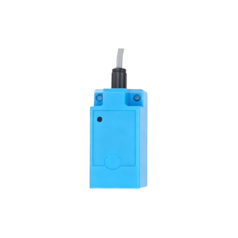
2. Excessive Current (Overcurrent): Connecting a load that draws more current than the sensor's output can handle will cause the output stage to overheat and fail. This often happens when the connected load, like a relay coil or PLC input module, has an inrush current higher than the sensor's rated switching capacity or if a short circuit occurs in the load wiring.
3. Incorrect Wiring: Improper connection is a leading cause of immediate failure. Common wiring errors include:
Reverse Polarity: Connecting DC supply wires (+V and 0V) incorrectly to a DC sensor.
AC/DC Mismatch: Applying an AC voltage to a DC-rated sensor, or vice versa.
Connecting Load to the Wrong Terminal: For 3-wire sensors, mistakenly connecting the load between the supply positive and the sensor's output, instead of between the output and supply negative (for NPN type) or positive (for PNP type).
4. Inductive Load Without Protection: When switching inductive loads (relays, solenoids), the collapse of the magnetic field generates a high reverse voltage spike (back EMF). Without a protective circuit like a freewheeling diode (for DC) or a surge suppressor (for AC), this spike can destroy the sensor's output.
5. Environmental Factors: While not always causing instant "burnout," extreme heat can degrade components over time, leading to thermal runaway and failure. Contamination with conductive dust or metallic chips can also cause internal short circuits.
Systematic Troubleshooting Steps When a Sensor Fails:
1. Immediate Safety First: De-energize and lock out the power supply to the entire circuit or machine. Confirm zero voltage using a multimeter.
2. Visual and Olfactory Inspection: Examine the failed sensor for obvious signs: cracks, melting, scorch marks, or a burnt smell. Check the connector and cable for damage.
3. Verify Power Supply: Before installing a new sensor, measure the supply voltage at the connection point. Ensure it is stable, within the sensor's specified range (e.g., 10-30V DC), and free from excessive noise or ripple.
4. Check the Load: Measure the resistance or impedance of the connected load (e.g., PLC input, relay coil). Calculate or measure its current draw to ensure it is below the sensor's maximum switching current. For inductive loads, verify the presence and correct orientation of a suppression diode or other protective device.
5. Inspect Wiring: Meticulously review the wiring diagram. Confirm all connections are correct, tight, and free from corrosion. Use a continuity tester to check for short circuits or ground faults in the cabling.
6. Replace and Test: Install a new sensor of the correct type (NPN/PNP, NO/NC, voltage, current rating). Temporarily power the circuit and test its operation with the target object before reintegrating it into the full system. Monitor the sensor's temperature during initial operation.
Prevention and Best Practices:
Preventing burnout is far more cost-effective than reactive troubleshooting. Implement these strategies:
Select the Right Sensor: Choose a sensor with a voltage and current rating with a sufficient safety margin (derating). For harsh electrical environments, select models with built-in surge protection or robust protection circuits.
Implement External Protection: Always