In the realm of industrial automation and control systems, proximity sensors are indispensable components. Their primary function is to detect the presence or absence of an object without physical contact, relying on changes in an electromagnetic field or beam. The true utility of these sensors, however, is unlocked through their conversion methods—the processes by which the detected physical phenomenon is transformed into a usable electrical signal. Understanding these conversion principles is crucial for selecting the right sensor for an application and ensuring reliable system integration.
The most fundamental categorization of proximity sensors is based on their underlying conversion technology. Each type employs a distinct physical principle to achieve non-contact detection, leading to specific performance characteristics, advantages, and limitations.
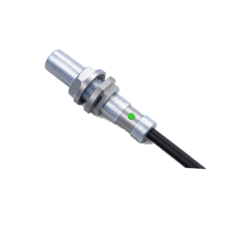
Inductive Proximity Sensors operate on the principle of electromagnetic induction. The sensor's active face contains a coil that is part of an oscillator circuit, generating a high-frequency electromagnetic field. When a metallic object (ferrous or non-ferrous) enters this field, eddy currents are induced on the surface of the target. These eddy currents draw energy from the oscillator, causing a change in its amplitude or frequency. This change is then processed by an evaluation circuit, which triggers a solid-state switch (typically an NPN or PNP transistor) to change state. The output is a clean, digital signal indicating object presence. Key advantages include high switching frequency, robustness in harsh environments (resistant to dust, oil, and coolant), and insensitivity to non-metallic materials. They are predominantly used for detecting metals in machine tools, automotive assembly, and material handling.
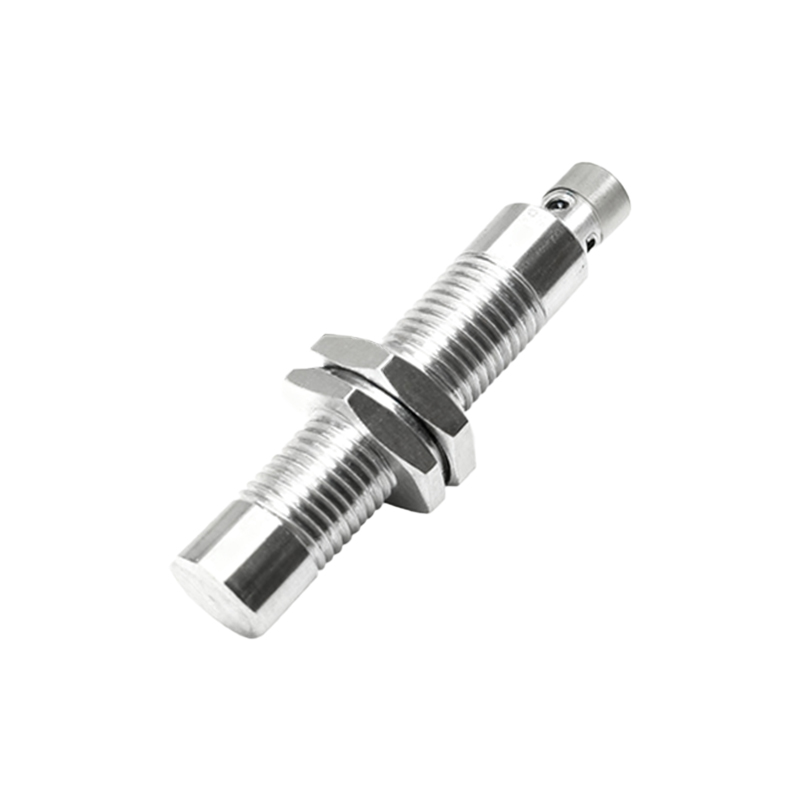
Capacitive Proximity Sensors function by detecting changes in capacitance. The sensor face acts as one plate of a capacitor, with the target object acting as the other plate, and the intervening space as the dielectric. The sensor generates an electrostatic field. When an object—be it metal, plastic, wood, liquid, or granular material—enters this field, it alters the dielectric constant and thus the capacitance of the system. This change is measured by an internal circuit, which subsequently switches the output. Capacitive sensors can detect a much wider range of materials compared to inductive types. They are ideal for applications involving non-metallic objects, such as level detection in plastic or glass containers, monitoring paper or wood thickness, or detecting filled vs. empty bottles on a conveyor line. Sensitivity adjustment is often available to tune out unwanted backgrounds like container walls.
Photoelectric Sensors utilize light as their detection medium. They consist of a light source (usually an LED emitting visible red, infrared, or laser light) and a receiver. The conversion method depends on the sensing mode. In the through-beam mode, the transmitter and receiver are separate units; detection occurs when the target object interrupts the light beam. This mode offers the longest sensing range and high reliability. In the retro-reflective mode, a single housing contains both emitter and receiver, and a reflector bounces the light back; detection occurs when the beam is broken. The diffuse (or proximity) mode also uses a single unit, but it detects light reflected directly off the target object itself. The receiver converts the received light intensity into an electrical current. An amplifier evaluates this signal against a set threshold to control the output. Photoelectric sensors are versatile, capable of detecting objects of almost any material, color, or finish, and are used extensively in packaging, pharmaceuticals, and logistics for object counting, positioning, and inspection.
Ultrasonic Proximity Sensors employ sound waves beyond the human hearing range. They contain a transducer that emits high-frequency ultrasonic pulses and then listens for the echo. The time interval between the emitted pulse and the received echo is measured (Time-of-Flight principle). This time is directly proportional to the distance to the target object. An internal microprocessor calculates this distance and compares it to preset switching thresholds to control the output. Unlike optical sensors, ultrasonic sensors are unaffected by color, transparency, or dust, and can reliably detect sound-absorbing materials. They excel in applications involving distance measurement, continuous level sensing of liquids or bulk solids, and detecting transparent objects like glass or clear films where photoelectric sensors may struggle.
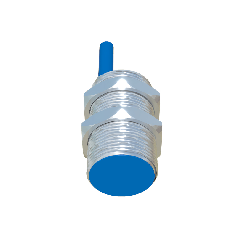
Beyond the core conversion principle, the output stage itself is a critical aspect of signal conversion. Most modern proximity sensors provide solid-state DC outputs (3-wire DC, 2-wire DC, or 4-wire Analog). The switching element converts the processed detection signal into a standard industrial control voltage (e.g., 10-30V DC). Analog outputs (4-20 mA or 0-10V) provide a continuous signal proportional to the distance to the target, enabling precise positioning or scaling applications.
Selecting the appropriate conversion method hinges on several application-specific factors: the target material, required sensing distance, environmental conditions (presence of contaminants, temperature, humidity), required switching