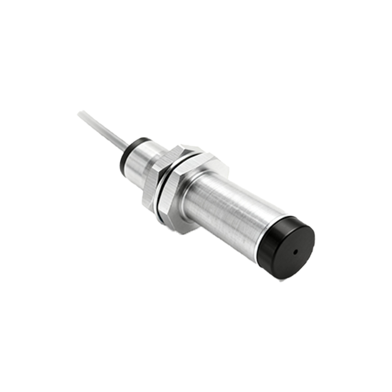
In the realm of industrial automation and electrical engineering, the reliable installation of sensing components is paramount to system integrity. The S1141 inductive proximity sensor, a staple in detection and positioning applications, demands particular attention during its integration, especially concerning its electrical and mechanical connection. While often supplied with pre-attached cables or connectors, field replacement, custom cable lengths, or repair scenarios necessitate a proper understanding of welding or, more accurately, soldering techniques for its lead wires. This guide details the recommended methods for terminating the leads of an S1141 proximity sensor, ensuring optimal performance and longevity.
First and foremost, it is critical to distinguish terminology. In this context, "welding" typically refers to the electrical connection process for the sensor's wires, which is technically precision soldering, not arc or fusion welding. The S1141 sensor leads are usually thin, stranded, or sometimes solid-core copper wires, insulated and color-coded (commonly brown for +V, blue for 0V/common, and black for the output signal). The core objective is to create a permanent, low-resistance, and mechanically robust electrical joint without damaging the internal circuitry of the sensor.
Essential Tools and Materials:
A successful soldering operation requires preparation. You will need:
A temperature-controlled soldering iron (recommended wattage 25-40W) with a fine tip.
High-quality, rosin-core solder (60/40 tin-lead or lead-free alternative, with a diameter suitable for fine electronics work).
Heat-shrink tubing in various diameters (with adhesive lining preferred for environmental sealing).
A wire stripper and cutter.
A pair of helping hands or a clamp to hold components steady.
Isopropyl alcohol and a brush for cleaning flux residue.
Pre-Soldering Preparation:
1. Sensor Preparation: Carefully examine the sensor body. The leads protrude from a sealed entry point. Avoid applying excessive mechanical stress or bending directly at this gland, as it can compromise the sensor's ingress protection (IP rating).
2. Wire Stripping: Strip approximately 3-5 mm of insulation from the end of each sensor lead. Use a wire stripper calibrated to the wire gauge to avoid nicking or cutting the copper strands. For stranded wire, gently twist the strands to keep them together.
3. Tin the Wires: Apply a small amount of solder to the exposed strands of the sensor wire—a process called "tinning." Briefly touch the soldering iron tip to the wire, then apply the solder to the wire, not the iron. This coats the strands, preventing fraying and ensuring better solder flow in the final joint. Avoid excessive solder which can make the wire rigid.
4. Prepare the Destination: Whether connecting to a terminal block, a connector pin, or another cable, ensure the destination point is clean and, if applicable, pre-tinned.
The Soldering Process:
The key is speed and precision to minimize heat transfer to the sensor.
1. Secure Components: Firmly secure both the tinned sensor lead and the destination connection point (e.g., a connector pin) using the helping hands. Ensure a stable mechanical connection before applying solder; the wires should be physically held in contact.
2. Apply Heat and Solder: Touch the tip of the soldering iron to the combined metals (e.g., wire and terminal) to heat them both evenly. After 1-2 seconds, apply the solder wire to the junction of the components, not directly to the iron tip. The solder should melt and flow smoothly, wicking into the joint and forming a concave, shiny fillet. The entire process should not exceed 3-4 seconds per wire.
3. Cool and Inspect: Remove the solder first, then the iron. Hold the joint steady until the solder solidifies completely (do not blow on it). A good solder joint should be bright, smooth, and fully cover the connection without blobs, spikes, or a dull, grainy appearance (cold solder joint).
Post-Soldering Insulation and Protection:
This step is crucial for the S1141, which is often used in harsh industrial environments.
1. Clean the Joint: Use a brush dipped in isopropyl alcohol to remove any residual flux from the soldered joint. Flux residue can be corrosive over time.
2. Apply Heat-Shrink Tubing: Slide an appropriate diameter of heat-shrink tubing over the joint before soldering if possible, or over one wire beforehand. After soldering and cleaning, center the tubing over the exposed metal and the wire insulation. Apply heat evenly from a heat gun until the tubing shrinks tightly and any adhesive lining melts to form