In industrial automation and control systems, the integration of proximity sensors with relays is a fundamental yet critical task. This connection forms the backbone of countless applications, from simple object detection triggering an alarm to complex sequential machine control. A proximity sensor, being a solid-state device, outputs a discrete signal upon detecting a target within its sensing range. However, this signal often lacks the current or voltage capacity to directly drive larger loads like motors, solenoids, or indicator lamps. This is where the electromechanical relay comes in, acting as a robust intermediary switch controlled by the sensor's signal.
The first step is understanding the sensor's output type. The two most common configurations are PNP (sourcing) and NPN (sinking) for DC sensors. A PNP sensor switches the positive voltage to its output wire when activated, while an NPN sensor switches the negative or ground. This distinction is paramount for correct wiring to the relay coil. For AC sensors, the output is typically a switched AC line. Always consult the sensor's datasheet for its output specifications: voltage rating, current capacity (often around 100-200mA), and whether it is normally open (NO) or normally closed (NC).
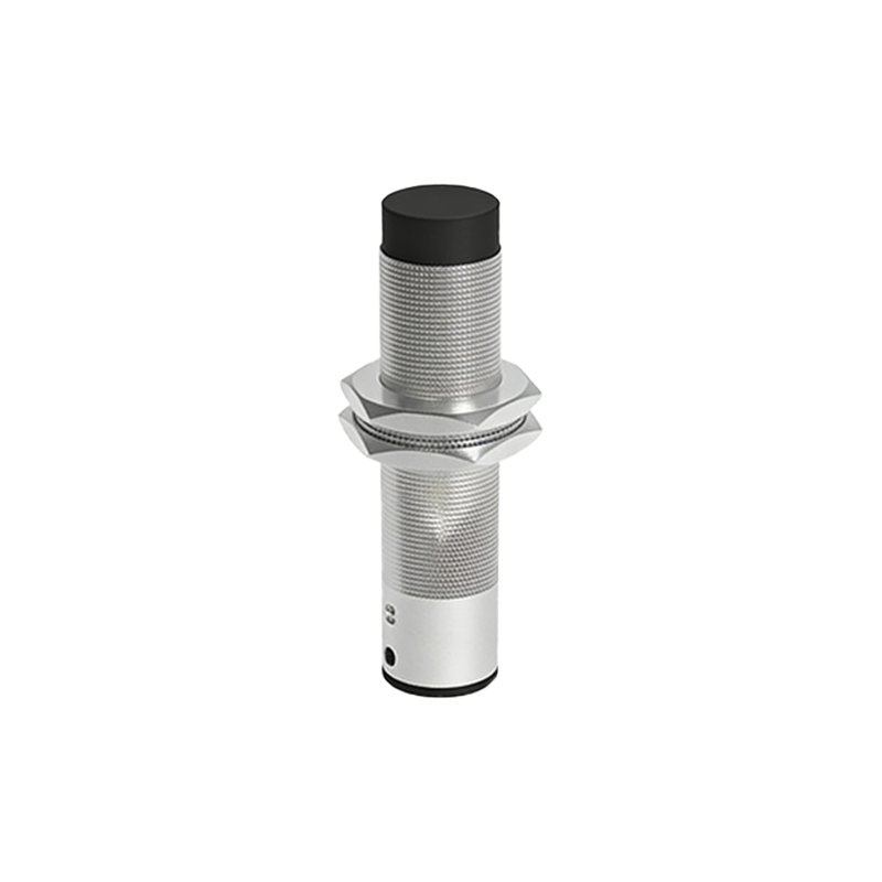
A standard relay has a coil (the control input) and a set of contact terminals (the switched output). The coil is rated for a specific voltage (e.g., 12VDC, 24VDC/AC). The goal is to use the sensor's output to power this coil. Let's outline a typical wiring procedure for a DC system using a PNP sensor and a 24VDC relay.
1. Power Supply Connections: Establish a stable DC power source. Connect the positive terminal (+) of the 24VDC supply to the positive wire (typically brown) of the proximity sensor. Connect the negative terminal (-) of the supply to one terminal of the relay coil.
2. Sensor to Relay Connection: Connect the output wire (typically black) of the PNP sensor to the other terminal of the relay coil.
3. Sensor Common Completion: Connect the negative/common wire (typically blue) of the sensor directly to the negative terminal (-) of the power supply.
4. Relay Contact Circuit: Wire the load (e.g., a motor starter coil) in series with the main power and the relay's normally open (NO) contact terminals. A separate fuse or circuit breaker should protect this load circuit.
Circuit Operation: When the sensor detects a target, its internal transistor switches, allowing current to flow from its positive supply, out through its output wire, through the relay coil, and back to the power supply negative. This energizes the relay coil, causing its armature to move and close the NO contacts in the separate load circuit, thus powering the connected device.
For an NPN sensor, the wiring logic is inverted. The relay coil would be connected between the positive supply and the sensor's output. When the NPN sensor activates, it completes the path to ground, allowing current to flow through the coil to ground, thereby energizing it.
Several key considerations ensure reliable operation. First, flyback diode protection is essential for DC relays. A diode (like a 1N4007) must be installed across the relay coil terminals with the cathode (striped end) toward the positive side. This diode suppresses the high-voltage transient spike generated when the coil is de-energized, protecting the sensor's output transistor from damage. Second, verify that the sensor's maximum output current is not exceeded by the relay coil's inrush and holding current. If the coil current is too high, an intermediate amplifier or a solid-state relay with lower control current requirements may be necessary. Third, maintain proper segregation of wiring. Keep the low-current sensor/relay coil wires separate from high-current load wires to avoid electromagnetic interference inducing false signals. Use conduit or cable trays for organization and safety.
Troubleshooting often involves systematic checks. Use a multimeter to verify power supply voltage at the sensor and relay. Check for the presence of the output signal from the sensor when a target is presented. Listen for the audible click of the relay pulling in. If the relay chatters or fails to hold, it may indicate insufficient current from the sensor or a voltage drop in the control circuit. Ensure all connections are tight and corrosion-free.
In summary, connecting a proximity sensor to a relay is a straightforward process of using the sensor as a switch for the relay's coil circuit. Success hinges on correctly matching the sensor's output type (PNP/NPN) with the relay coil wiring, incorporating protective components like a flyback diode, and adhering to sound electrical practices for noise immunity and safety. This reliable pairing