Proximity sensors are widely used in industrial automation for detecting the presence or absence of an object without physical contact. Among the various configurations, the Normally Open (NO) type is a common choice for many applications, such as conveyor systems, machine safety, and position sensing. Understanding how to properly wire a Normally Open proximity sensor is crucial for ensuring reliable operation and system safety. This article provides a step-by-step guide on wiring a NO proximity sensor, covering essential principles, practical considerations, and troubleshooting tips.
First, it is important to clarify what "Normally Open" means in the context of proximity sensors. A Normally Open sensor has an output circuit that remains open (non-conductive) when no target is detected. When a target enters the sensing range, the output circuit closes (becomes conductive), allowing current to flow. This behavior is opposite to that of a Normally Closed (NC) sensor, where the output circuit is closed by default and opens when a target is detected. NO sensors are often preferred in applications where an active signal is required only upon detection, such as triggering an alarm or starting a process.
Before starting the wiring process, gather the necessary tools and components: a NO proximity sensor (inductive, capacitive, or ultrasonic, depending on the application), a power supply compatible with the sensor's voltage rating (commonly 12-24V DC or 110-240V AC), connecting wires, a load device (e.g., a relay, PLC input, or indicator light), and appropriate safety gear. Always refer to the sensor's datasheet for specific specifications, including wiring diagrams, voltage limits, and output current capacity.
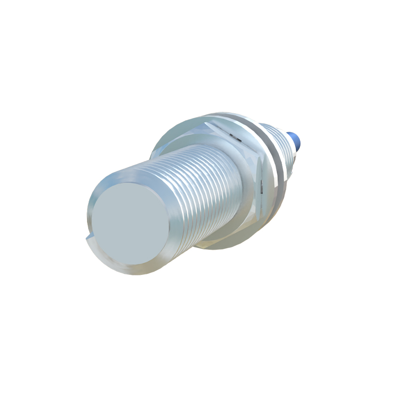
The basic wiring setup for a NO proximity sensor involves three main connections: power supply, load, and ground. For a typical DC sensor, follow these steps:
1. Power Connection: Connect the positive terminal of the power supply to the sensor's positive wire (usually labeled V+ or brown wire). Connect the negative terminal of the power supply to the sensor's negative wire (usually labeled V- or blue wire). This provides the operating voltage for the sensor's internal circuitry.
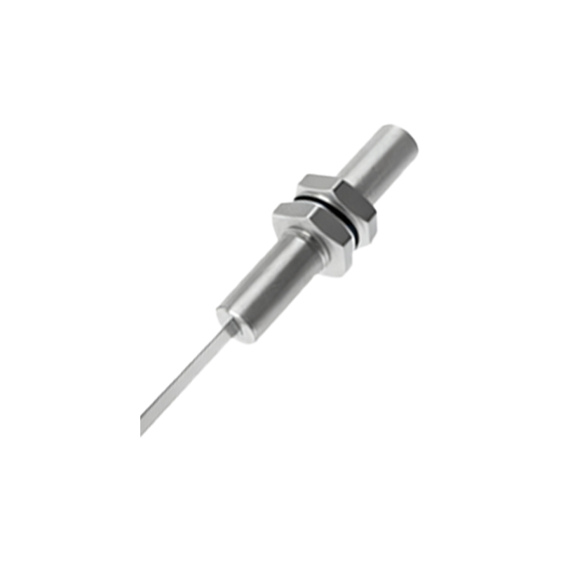
2. Load Connection: Connect the sensor's output wire (often black or white) to one terminal of the load device. The other terminal of the load should be connected to the positive side of the power supply (for DC) or the live wire (for AC), depending on the circuit design. When the sensor detects a target, the output closes, completing the circuit and activating the load.
3. Grounding: Ensure proper grounding by connecting the sensor's ground wire (if available) to a reliable earth ground. This minimizes electrical noise and enhances safety.
In AC sensor wiring, similar principles apply, but attention must be paid to phase and neutral connections. Typically, the brown wire connects to the live phase, the blue wire to neutral, and the black output wire to the load. Always verify the sensor's wiring diagram to avoid mistakes, as incorrect connections can damage the sensor or cause malfunctions.
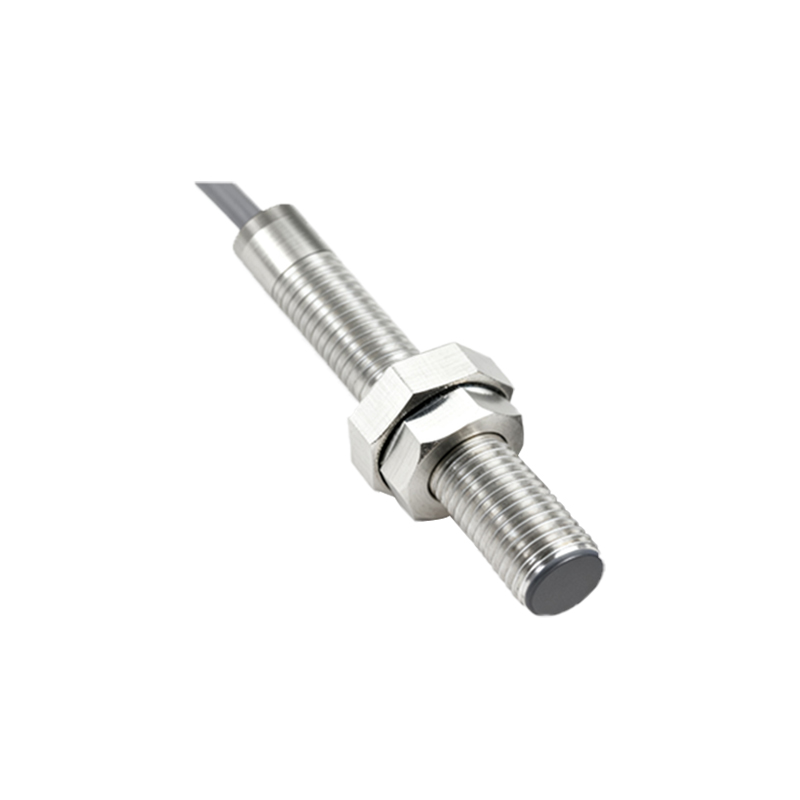
When integrating a NO proximity sensor into a control system, such as a Programmable Logic Controller (PLC), the wiring may involve additional considerations. For PLC input modules, connect the sensor output to the PLC input terminal and the common terminal to the power supply. Ensure the sensor's output type (e.g., NPN or PNP for DC sensors) matches the PLC input requirements. NPN sensors sink current to ground, while PNP sensors source current from positive voltage; using an incompatible type can lead to improper operation.
Practical tips for successful wiring include:
- Use shielded cables for long wire runs to reduce electromagnetic interference.
- Keep sensor cables away from high-voltage lines to prevent noise induction.
- Install surge protectors in environments with frequent voltage spikes.
- Test the sensor with a multimeter before full system integration to confirm output switching.
Common issues in NO proximity sensor wiring include false triggering, no output signal, or intermittent operation. Troubleshooting steps involve checking power supply stability, verifying wiring connections, inspecting for sensor damage or contamination, and ensuring the target material and size are within specifications. For inductive sensors, only metallic targets are detectable, while capacitive sensors can sense non-metallic objects. Adjust the sensing distance if needed, as environmental factors like temperature or humidity may affect performance.
In summary, wiring a Normally Open proximity sensor requires careful attention to electrical connections, sensor type, and application requirements. By following standard practices and manufacturer guidelines, engineers can achieve reliable detection and enhance automation system efficiency. Regular maintenance and testing further ensure long-term performance, making NO proximity sensors a valuable component in modern industrial setups.