Proximity sensors are fundamental components in modern industrial automation, safety systems, and countless electronic devices. Understanding their schematic diagrams is crucial for engineers involved in design, troubleshooting, and integration. This article delves into the core operating principles and typical circuit configurations of common proximity sensor types, providing a detailed analysis of their schematic representations.
At its heart, a proximity sensor detects the presence or absence of a nearby object without physical contact. The schematic diagram translates this function into an electrical blueprint. The most prevalent types are inductive, capacitive, and photoelectric sensors, each with distinct schematic symbols and circuit topologies.
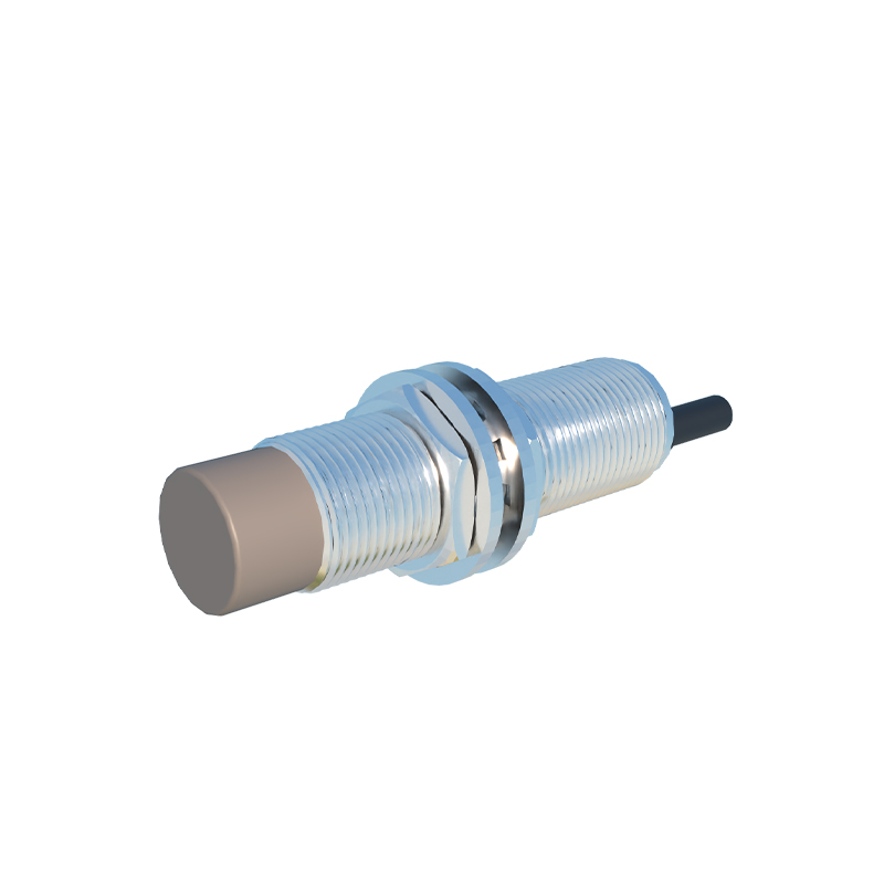
Inductive Proximity Sensor Schematic
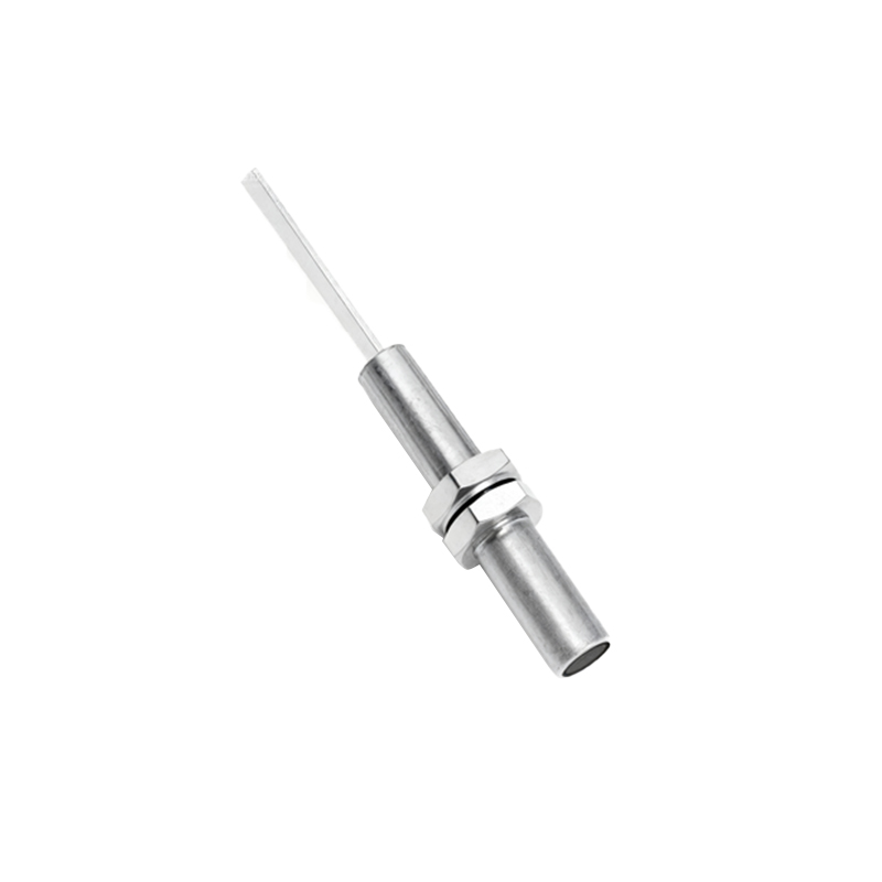
Inductive sensors detect metallic objects. The core of the schematic is an LC oscillator circuit, where 'L' represents the sensing coil (often depicted as an inductor symbol with a core) and 'C' is a capacitor. This oscillator generates a high-frequency electromagnetic field at the sensor's active face. In a standard three-wire DC sensor schematic, you will typically see:
Power Supply Connections: V+ (typically 10-30V DC) and V- (0V/GND).
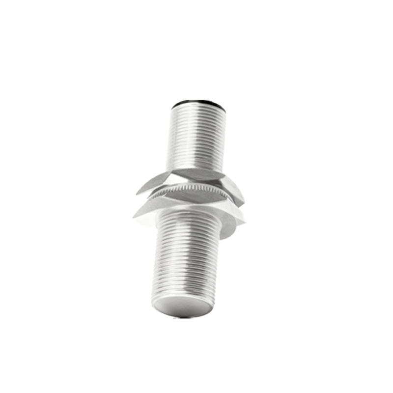
The Oscillator Block: Drawn as an inductor in parallel with a capacitor, connected to an oscillator IC or transistor circuit that sustains the oscillation.
The Detection Circuit: This monitors the amplitude of the oscillation. When a metal object enters the field, eddy currents are induced in the object, damping the oscillation. This amplitude change is detected.
The Output Stage: The detection signal triggers a switching element. In an NPN (sinking) output schematic, the output line is connected to the collector of an NPN transistor, with the emitter to V-. The load is connected between V+ and the output terminal. For a PNP (sourcing) output, a PNP transistor is used with its emitter to V+ and the load between the output and V-. The output is often protected by a flyback diode and may include status LEDs in the diagram.
Capacitive Proximity Sensor Schematic
Capacitive sensors can detect both metallic and non-metallic materials (plastics, liquids, etc.). Their schematic is similar to inductive types but based on a capacitive sensing principle. The sensing element forms one plate of a capacitor, with the target object acting as the other plate. The schematic includes:
The RC Oscillator: Instead of a pure LC circuit, the frequency is often determined by a resistor-capacitor network where the sensing capacitance is part of the 'C'.
The Sensing Electrode: Symbolically, it may be represented as a capacitor plate. The circuit measures changes in the capacitance of this electrode relative to ground. As an object approaches, the capacitance increases.
The Evaluation Circuitry: This circuit, often involving a specialized IC or comparator, detects the shift in the oscillator's frequency or charge/discharge time.
The Output Stage: Identical in configuration to the inductive sensor's output stage (NPN or PNP transistor switch), activated when the capacitance change exceeds a set threshold.
Photoelectric Sensor Schematic
Photoelectric sensors use light beams. Their schematics are more complex, clearly separating the transmitter and receiver sections.
Transmitter Side: Shows an LED (often infrared) as the light source, driven by a constant current circuit to ensure stable light intensity. It includes a series current-limiting resistor.
Receiver Side: For a diffuse or retro-reflective sensor, this shows a phototransistor or photodiode. The component is typically biased. When light falls on it, its conductivity changes.
Amplifier and Comparator: The small signal from the receiver is fed into a high-gain amplifier and then to a comparator circuit. The comparator compares the signal level to a preset threshold (adjustable for sensitivity).
Output Stage: Again, a transistor-based switch (NPN/PNP) is controlled by the comparator's output. Through-beam types have separate schematics for the standalone transmitter and receiver units.
Key Schematic Symbols and Annotations
Engineers must recognize standard symbols: the inductor coil for inductive sensing, a capacitor plate icon for capacitive, and the diode/transistor symbols with light arrows for photoelectric components. Schematics also include protection devices like Zener diodes for over-voltage, RC snubbers for AC models, and short-circuit protection circuits. Wiring color codes (Brown/V+, Blue/V-, Black/Output) are frequently noted.
Analysis and Troubleshooting via Schematic
A thorough understanding of the schematic allows for systematic troubleshooting. For instance, if an inductive sensor fails to trigger, an engineer would use the schematic to:
1. Verify power at V+ and V-.
2. Check if the oscillator is active (using an