In industrial automation and control systems, proximity sensors are indispensable components for detecting the presence or absence of objects without physical contact. Their reliable operation hinges on correct sensitivity settings. An improperly adjusted sensor can lead to false triggers, missed detections, production downtime, and even safety hazards. This guide provides a detailed, practical walkthrough for engineers on how to correctly adjust the sensitivity of various types of proximity sensors, ensuring optimal performance in demanding applications.
Understanding Sensitivity and Its Key Influencers
Sensitivity, in the context of proximity sensors, refers to the maximum distance (the nominal sensing distance, Sn) at which the sensor can reliably detect a standard target. It is not merely a "range" knob but a calibration point that defines the sensor's operational window. Several critical factors influence the effective sensing range and must be considered before adjustment:
1. Target Material: Inductive sensors are optimized for ferrous metals (like mild steel). For non-ferrous metals (aluminum, copper, brass) or stainless steel, the effective sensing distance is reduced. Capacitive sensors are affected by the target's dielectric constant.
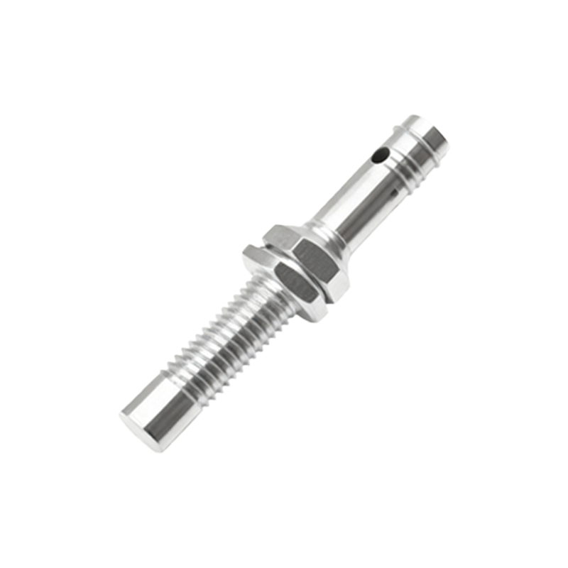
2. Target Size and Shape: The standard target is defined as a square of ferrous metal (Fe360) with a side length equal to the diameter of the sensing face or three times the rated sensing distance, whichever is greater. Smaller targets reduce the effective range.
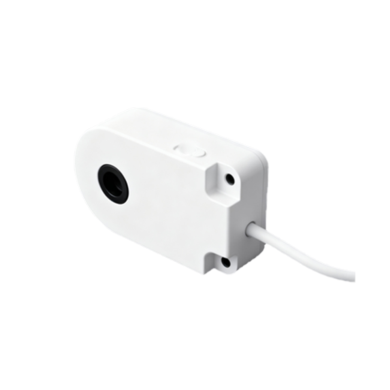
3. Mounting Conditions: Flush-mounted (embedded in metal) inductive sensors have a reduced sensing range compared to non-flush mountable types. Adjacent metal, other sensors, or power cables can cause electromagnetic interference and shielding effects.
4. Environmental Conditions: Temperature extremes, humidity, dust, oil, and chemical vapors can affect sensor performance. For instance, capacitive sensors are highly sensitive to environmental humidity changes.
5. Supply Voltage: While modern sensors are largely voltage-stable, operating at the extremes of the voltage range can marginally affect the switching point.
Adjustment Procedures by Sensor Type
1. Inductive Proximity Sensors
These sensors detect metallic objects. Many modern inductive sensors feature a built-in potentiometer or a teach-in function.
Using a Potentiometer: Locate the sensitivity adjustment screw or potentiometer, often marked with a "+" and "-" or a lock symbol. Use a small screwdriver.
Procedure: Present the standard target at the desired trigger distance. Slowly turn the potentiometer clockwise ("+") until the sensor's output LED activates. Then, slowly turn it counterclockwise ("-") until the LED just deactivates. The optimal setting is typically midway between these two points. This provides a buffer against minor target position variations and temperature drift.
Best Practice: Always adjust with the actual target material and under normal operating conditions. Verify the setting by moving the target in and out of the sensing field multiple times.
Using Teach-In Function: Advanced sensors feature push-button or remote teach-in via IO-Link or a discrete input.
Two-Point Teach: This method defines the switch-on and switch-off points. Activate the teach mode, place the target at the maximum desired detection point (Far Point), and confirm. Then, place the target at the minimum desired release point (Near Point), and confirm. The sensor calculates the optimal hysteresis.
One-Point Teach: Simply place the target at the desired operating point and activate the teach function. The sensor sets its threshold relative to this reference.
2. Capacitive Proximity Sensors
Used for detecting non-metallic materials (plastics, liquids, wood, granules), these sensors are adjusted similarly but are more sensitive to environmental factors.
Procedure: Capacitive sensors usually have a sensitivity potentiometer. Start with the potentiometer at its minimum setting (fully counterclockwise). Slowly increase the sensitivity (clockwise) until the sensor reliably detects the target material at the required distance. Crucial Step: After setting for the target, introduce the non-target background (e.g., the container wall) to ensure the sensor does not false-trigger. Fine-tune to reject the background while still sensing the target. A shielding electrode (if available) should be grounded to focus the field.
3. Ultrasonic Proximity Sensors
These sensors measure time-of-flight and have adjustable sensing windows (upper and lower limits).
Procedure: Using push buttons or a configuration tool, set the Near Limit (the point inside which an object is considered present) and the Far Limit (the point beyond which an object is ignored). The space between is the sensing window. For simple on/off detection, set a narrow window around the desired detection point. Adjust the response time to filter out noise but ensure it